


1–1–9 Instrument Landing System (ILS)
a. General
1. The ILS is designed to provide an approach path for exact alignment and descent of an aircraft on final approach to a runway.
2. The basic components of an ILS are the localizer, glide slope, and Outer Marker (OM) and, when installed for use with Category II or Category III instrument approach procedures, an Inner Marker (IM).
3. The system may be divided functionally into three parts:
(a) Guidance information: localizer, glide slope.
(b) Range information: marker beacon, DME.
(c) Visual information: approach lights, touchdown and centerline lights, runway lights.
4. The following means may be used to substitute for the OM:
(a) Compass locator; or
(b) Precision Approach Radar (PAR); or
(c) Airport Surveillance Radar (ASR); or
(d) Distance Measuring Equipment (DME), Very High Frequency Omni-directional Range (VOR), or Nondirectional beacon fixes authorized in the Standard Instrument Approach Procedure; or
(e) Very High Frequency Omni-directional Radio Range (VOR); or
(f) Nondirectional beacon fixes authorized in the Standard Instrument Approach Procedure; or
(g) A suitable RNAV system with Global Positioning System (GPS), capable of fix identification on a Standard Instrument Approach Procedure.
5. Where a complete ILS system is installed on each end of a runway; (i.e., the approach end of Runway 4 and the approach end of Runway 22) the ILS systems are not in service simultaneously.
b. Localizer
1. The localizer transmitter operates on one of 40 ILS channels within the frequency range of 108.10 to 111.95 MHz. Signals provide the pilot with course guidance to the runway centerline.
2. The approach course of the localizer is called the front course and is used with other functional parts, e.g., glide slope, marker beacons, etc. The localizer signal is transmitted at the far end of the runway. It is adjusted for a course width of (full scale fly-left to a full scale fly-right) of 700 feet at the runway threshold.
3. The course line along the extended centerline of a runway, in the opposite direction to the front course is called the back course.
Caution: Unless the aircraft’s ILS equipment includes reverse sensing capability, when flying inbound on the back course it is necessary to steer the aircraft in the direction opposite the needle deflection when making corrections from off-course to on-course. This “flying away from the needle” is also required when flying outbound on the front course of the localizer. Do not use back course signals for approach unless a back course approach procedure is published for that particular runway and the approach is authorized by ATC.
4. Identification is in International Morse Code and consists of a three-letter identifier preceded by the letter I (• •) transmitted on the localizer frequency.
Example: I-DIA
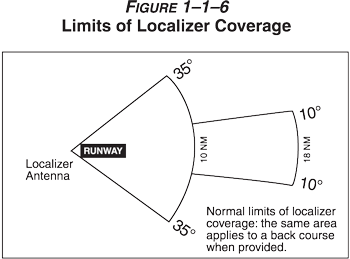
5. The localizer provides course guidance throughout the descent path to the runway threshold from a distance of 18 NM from the antenna between an altitude of 1,000 feet above the highest terrain along the course line and 4,500 feet above the elevation of the antenna site. Proper off-course indications are provided throughout the following angular areas of the operational service volume:
(a) To 10 degrees either side of the course along a radius of 18 NM from the antenna; and
(b) From 10 to 35 degrees either side of the course along a radius of 10 NM. (See Figure 1-1-6.)
6. Unreliable signals may be received outside of these areas. ATC may clear aircraft on procedures beyond the service volume when the controller initiates the action or when the pilot requests, and radar monitoring is provided.
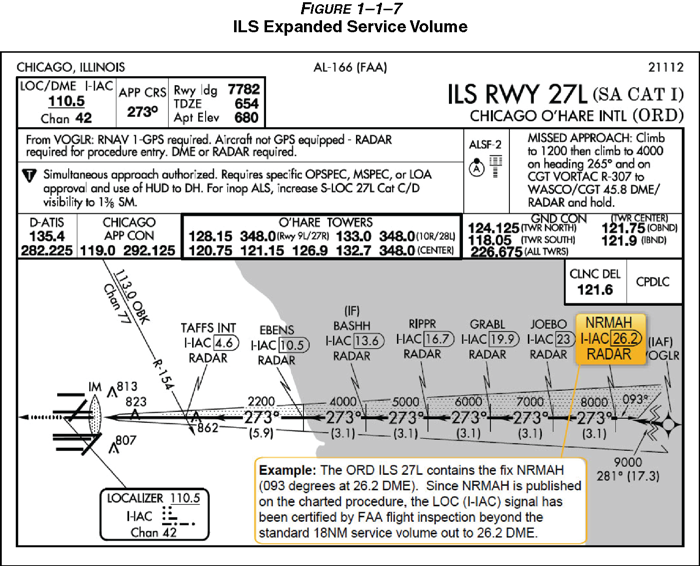
7. The areas described in paragraph 1-1-9 b5 and depicted in Figure 1-1-6 represent a Standard Service Volume (SSV) localizer. All charted procedures with localizer coverage beyond the 18 NM SSV have been through the approval process for Expanded Service Volume (ESV), and have been validated by flight inspection. (See Figure 1-1-7.)
c. Localizer Type Directional Aid (LDA)
1. The LDA is of comparable use and accuracy to a localizer but is not part of a complete ILS. The LDA course usually provides a more precise approach course than the similar Simplified Directional Facility (SDF) installation, which may have a course width of 6 or 12 degrees.
2. The LDA is not aligned with the runway. Straight-in minimums may be published where alignment does not exceed 30 degrees between the course and runway. Circling minimums only are published where this alignment exceeds 30 degrees.
3. A very limited number of LDA approaches also incorporate a glideslope. These are annotated in the plan view of the instrument approach chart with a note, “LDA/Glideslope.” These procedures fall under a newly defined category of approaches called Approach with Vertical Guidance (APV) described in paragraph 5-4-5, Instrument Approach Procedure Charts, subparagraph a7(b), Approach with Vertical Guidance (APV). LDA minima for with and without glideslope is provided and annotated on the minima lines of the approach chart as S-LDA/GS and S-LDA. Because the final approach course is not aligned with the runway centerline, additional maneuvering will be required compared to an ILS approach.
d. Glide Slope/Glide Path
1. The UHF glide slope transmitter, operating on one of the 40 ILS channels within the frequency range 329.15 MHz, to 335.00 MHz radiates its signals in the direction of the localizer front course. The term “glide path” means that portion of the glide slope that intersects the localizer.
Caution: False glide slope signals may exist in the area of the localizer back course approach which can cause the glide slope flag alarm to disappear and present unreliable glide slope information. Disregard all glide slope signal indications when making a localizer back course approach unless a glide slope is specified on the approach and landing chart.
2. The glide slope transmitter is located between 750 feet and 1,250 feet from the approach end of the runway (down the runway) and offset 250 to 650 feet from the runway centerline. It transmits a glide path beam 1.4 degrees wide (vertically). The signal provides descent information for navigation down to the lowest authorized decision height (DH) specified in the approved ILS approach procedure. The glidepath may not be suitable for navigation below the lowest authorized DH and any reference to glidepath indications below that height must be supplemented by visual reference to the runway environment. Glidepaths with no published DH are usable to runway threshold.
3. The glide path projection angle is normally adjusted to 3 degrees above horizontal so that it intersects the MM at about 200 feet and the OM at about 1,400 feet above the runway elevation. The glide slope is normally usable to the distance of 10 NM. However, at some locations, the glide slope has been certified for an extended service volume which exceeds 10 NM.
4. Pilots must be alert when approaching the glidepath interception. False courses and reverse sensing will occur at angles considerably greater than the published path.
5. Make every effort to remain on the indicated glide path.
Caution: Avoid flying below the glide path to assure obstacle/terrain clearance is maintained.
6. The published glide slope threshold crossing height (TCH) DOES NOT represent the height of the actual glide path on-course indication above the runway threshold. It is used as a reference for planning purposes which represents the height above the runway threshold that an aircraft’s glide slope antenna should be, if that aircraft remains on a trajectory formed by the four-mile-to-middle marker glidepath segment.
7. Pilots must be aware of the vertical height between the aircraft’s glide slope antenna and the main gear in the landing configuration and, at the DH, plan to adjust the descent angle accordingly if the published TCH indicates the wheel crossing height over the runway threshold may not be satisfactory. Tests indicate a comfortable wheel crossing height is approximately 20 to 30 feet, depending on the type of aircraft.
Note: The TCH for a runway is established based on several factors including the largest aircraft category that normally uses the runway, how airport layout affects the glide slope antenna placement, and terrain. A higher than optimum TCH, with the same glide path angle, may cause the aircraft to touch down further from the threshold if the trajectory of the approach is maintained until the flare. Pilots should consider the effect of a high TCH on the runway available for stopping the aircraft.
e. Distance Measuring Equipment (DME)
1. When installed with the ILS and specified in the approach procedure, DME may be used:
(a) In lieu of the OM;
(b) As a back course (BC) final approach fix (FAF); and
(c) To establish other fixes on the localizer course.
2. In some cases, DME from a separate facility may be used within Terminal Instrument Procedures (TERPS) limitations:
(a) To provide ARC initial approach segments;
(b) As a FAF for BC approaches; and
(c) As a substitute for the OM.
f. Marker Beacon
1. ILS marker beacons have a rated power output of 3 watts or less and an antenna array designed to produce an elliptical pattern with dimensions, at 1,000 feet above the antenna, of approximately 2,400 feet in width and 4,200 feet in length. Airborne marker beacon receivers with a selective sensitivity feature should always be operated in the “low” sensitivity position for proper reception of ILS marker beacons.
2. ILS systems may have an associated OM. An MM is no longer required. Locations with a Category II ILS also have an Inner Marker (IM). Due to advances in both ground navigation equipment and airborne avionics, as well as the numerous means that may be used as a substitute for a marker beacon, the current requirements for the use of marker beacons are:
(a) An OM or suitable substitute identifies the Final Approach Fix (FAF) for nonprecision approach (NPA) operations (for example, localizer only); and
(b) The MM indicates a position approximately 3,500 feet from the landing threshold. This is also the position where an aircraft on the glide path will be at an altitude of approximately 200 feet above the elevation of the touchdown zone. An MM is no longer operationally required. There are some MMs still in use, but there are no MMs being installed at new ILS sites by the FAA; and
(c) An IM, where installed, indicates the point at which an aircraft is at decision height on the glide path during a Category II ILS approach. An IM is only required for CAT II operations that do not have a published radio altitude (RA) minimum.
Table 1–1–3
Marker Passage Indications
|
Marker |
Code |
Light |
|
OM |
– – – |
Blue |
|
MM |
• – • – |
Amber |
|
IM |
• • • • |
White |
|
BC |
• • • • |
White |
3. A back course marker normally indicates the ILS back course final approach fix where approach descent is commenced.
g. Compass Locator
1. Compass locator transmitters are often situated at the MM and OM sites. The transmitters have a power of less than 25 watts, a range of at least 15 miles and operate between 190 and 535 kHz. At some locations, higher powered radio beacons, up to 400 watts, are used as OM compass locators.
2. Compass locators transmit two letter identification groups. The outer locator transmits the first two letters of the localizer identification group, and the middle locator transmits the last two letters of the localizer identification group.
h. ILS Frequency (See Table 1-1-4.)
Table 1–1–4
Frequency Pairs Allocated for ILS
|
Localizer MHz |
Glide Slope |
|
108.10 |
334.70 |
|
108.15 |
334.55 |
|
108.3 |
334.10 |
|
108.35 |
333.95 |
|
108.5 |
329.90 |
|
108.55 |
329.75 |
|
108.7 |
330.50 |
|
108.75 |
330.35 |
|
108.9 |
329.30 |
|
108.95 |
329.15 |
|
109.1 |
331.40 |
|
109.15 |
331.25 |
|
109.3 |
332.00 |
|
109.35 |
331.85 |
|
109.50 |
332.60 |
|
109.55 |
332.45 |
|
109.70 |
333.20 |
|
109.75 |
333.05 |
|
109.90 |
333.80 |
|
109.95 |
333.65 |
|
110.1 |
334.40 |
|
110.15 |
334.25 |
|
110.3 |
335.00 |
|
110.35 |
334.85 |
|
110.5 |
329.60 |
|
110.55 |
329.45 |
|
110.70 |
330.20 |
|
110.75 |
330.05 |
|
110.90 |
330.80 |
|
110.95 |
330.65 |
|
111.10 |
331.70 |
|
111.15 |
331.55 |
|
111.30 |
332.30 |
|
111.35 |
332.15 |
|
111.50 |
332.9 |
|
111.55 |
332.75 |
|
111.70 |
333.5 |
|
111.75 |
333.35 |
|
111.90 |
331.1 |
|
111.95 |
330.95 |
i. ILS Minimums
1. The lowest authorized ILS minimums, with all required ground and airborne systems components operative, are:
(a) Category I. Decision Height (DH) 200 feet and Runway Visual Range (RVR) 2,400 feet (with touchdown zone and centerline lighting, RVR 1,800 feet), or (with Autopilot or FD or HUD, RVR 1,800 feet);
(b) Special Authorization Category I. DH 150 feet and Runway Visual Range (RVR) 1,400 feet, HUD to DH;
(c) Category II. DH 100 feet and RVR 1,200 feet (with autoland or HUD to touchdown and noted on authorization, RVR 1,000 feet);
(d) Special Authorization Category II with Reduced Lighting. DH 100 feet and RVR 1,200 feet with autoland or HUD to touchdown and noted on authorization, (touchdown zone, centerline lighting and ALSF–2 are not required);
(e) Category IIIa. No DH or DH below 100 feet and RVR not less than 700 feet;
(f) Category IIIb. No DH or DH below 50 feet and RVR less than 700 feet but not less than 150 feet; and
(g) Category IIIc. No DH and no RVR limitation.
Note: Special authorization and equipment required for Categories II and III.
j. Inoperative ILS Components
1. Inoperative localizer. When the localizer fails, an ILS approach is not authorized.
2. Inoperative glide slope. When the glide slope fails, the ILS reverts to a nonprecision localizer approach.
Reference: See the inoperative component table in the U.S. Government Terminal Procedures Publication (TPP), for adjustments to minimums due to inoperative airborne or ground system equipment.
k. ILS Course and Glideslope Distortion
1. All pilots should be aware that ILS installations are subject to signal interference by surface vehicles and aircraft (either on the ground or airborne). ILS CRITICAL AREAS are established near each localizer and glide slope antenna. Pilots should be aware of the level of critical area protection they can expect in various weather conditions and understand that signal disturbances may occur as a result of normal airport operations irrespective of the official weather observation.
2. ATC is not always required to issue control instructions to avoid interfering operations within ILS critical areas at controlled airports during the hours the Airport Traffic Control Tower (ATCT) is in operation. ATC responsibilities vary depending on the official weather observation and are described as follows:
(a) Weather Conditions. Official weather observation indicates a ceiling of 800 feet or higher and visibility 2 miles or greater, no localizer or glideslope critical area protection is provided by ATC unless specifically requested by the flight crew.
(b) Weather Conditions. Official weather observation indicates a ceiling of less than 800 feet or visibility less than 2 miles.
(1) Holding. Aircraft holding below 5,000 feet between the outer marker and the airport may cause localizer signal variations for aircraft conducting the ILS approach. Accordingly, such holding will not be authorized by ATC.
(2) Localizer Critical Area. When an arriving aircraft is inside the outer marker (OM) or the fix used in lieu of the OM, vehicles and aircraft will not be authorized in or over the precision approach critical area except:
[a] A preceding arriving aircraft on the same or another runway may pass over or through the localizer critical area, and;
[b] A preceding departing aircraft or missed approach on the same or another runway may pass through or over the localizer critical area.
(3) Glide Slope Critical Area. ATC will not authorize vehicles or aircraft operations in or over the glideslope critical area when an arriving aircraft is inside the outer marker (OM), or the fix used in lieu of the OM, unless the arriving aircraft has reported the runway in sight and is circling or side-stepping to land on another runway.
(c) Weather Conditions. Official weather observation indicates a ceiling less than 200 feet or runway visual range (RVR) less than 2000 feet.
(1) Localizer Critical Area. In addition to the critical area protection described in 1-1-9k2(b) above, when an arriving aircraft is inside the middle marker (MM), or in the absence of a MM, ½ mile final, ATC will not authorize:
[a] A preceding arriving aircraft on the same or another runway to pass over or through the localizer critical area, or;
[b] A preceding departing aircraft or missed approach on the same or another runway to pass through or over the localizer critical area.
3. In order to ensure that pilot and controller expectations match with respect to critical area protection for a given approach and landing operation, a flight crew should advise the tower any time it intends to conduct any autoland operation or use an SA CAT I, any CAT II, or any CAT III line of minima anytime the official weather observation is at or above a ceiling of 800 feet and 2 miles visibility. If ATC is unable to protect the critical area, they will advise the flight crew.
Example: Denver Tower, United 1153, Request Autoland (runway) ATC replies with: United 1153, Denver Tower, Roger, Critical Areas not protected.
4. Pilots are cautioned that even when the critical areas are considered to be protected, unless the official weather observation including controller observations indicates a ceiling less than 200 feet or RVR less than 2000 feet, ATC may still authorize a preceding arriving, departing, or missed approach aircraft to pass through or over the localizer critical area and that this may cause signal disturbances that could result in an undesired aircraft state during the final stages of the approach, landing, and rollout.
5. Pilots are cautioned that vehicular traffic not subject to ATC may cause momentary deviation to ILS course or glide slope signals. Also, critical areas are not protected at uncontrolled airports or at airports with an operating control tower when weather or visibility conditions are above those requiring protective measures. Aircraft conducting coupled or autoland operations should be especially alert in monitoring automatic flight control systems and be prepared to intervene as necessary. (See Figure 1-1-8.)
Note: Unless otherwise coordinated through Flight Standards, ILS signals to Category I runways are not flight inspected below the point that is 100 feet less than the decision altitude (DA). Guidance signal anomalies may be encountered below this altitude.
