


25
Preparation for Flight

Figure 25-1 Discuss your planned flight.
Careful planning for a flight on instruments is important. Besides satisfying normal IFR requirements, an instrument pilot flying in clouds or at night must be conscious of high terrain or obstacles that cannot be seen, and ensure that a safe altitude above them is maintained.
You must be aware of the danger of icing (both airframe and carburetor icing) and take appropriate precautions; you must have an alternate airport in mind in case a diversion becomes necessary; and you must have sufficient fuel to get there, and still have a safety margin remaining in the tanks on arrival.
The best time to organize these things is prior to flight.
Flight planning procedures learned early in your basic training will have prepared you thoroughly. As a reminder of some of the vital points, a number of the review questions will test your knowledge in these areas. Do not be afraid to review previously learned knowledge! Always remember that, as pilot-in-command, you are responsible for the safety of the flight.
Preflight Considerations for an IFR Flight
Preflight considerations, which are all logical, include:
- Am I properly qualified (instrument rated and qualified for this airplane, instrument current)?
- Am I medically fit today?
- Is the airplane suitably equipped (serviceable radios, anti-icing equipment, lighting, etc.)?
- What is the weather? Are changes expected?
- Is the departure airport suitable for my operation?
- Is the destination airport suitable for my operation?
- Is an alternate airport required (or more than one)?
- What routes are suitable in terms of terrain, weather and available en route NAVAIDs?
- Are there any relevant NOTAMs (FDC, Class I, Class II)?
- Are there any Terminal Flight Restrictions (TFRs) for my planned route of flight?
- Prepare charts (DPs, en route charts, instrument approach charts, VFR sectionals, etc.).
- Compile a flight log with courses, distances, times, MEAs and cruising altitudes calculated.
- Compile a fuel log, with adequate fuel reserves.
- File an IFR flight plan.
- Prepare the airplane.
- Organize the cockpit for flight — select charts, ensure that a flashlight is kept handy for night flying, etc.
- Brief passengers.
En Route Charts
It is essential that you can read IFR charts quickly and accurately, and this takes practice. Study your own charts, and become familiar with the legend. Each chart carries an enormous amount of vital information concerning NAVAIDs, airways, safe altitudes, airports, airspace, and communications. You have the choice of FAA Aeronautical Information Services (AIS) or Jeppesen charts — we consider both types here. The instrument rating FAA Knowledge examination is based on FAA low-altitude en route charts.
Airports
Airports are shown on the en route charts, accompanied by some basic information, such as elevation. On FAA charts, an airport with blue or green text indicates there is a published instrument approach procedure for that airport. Brown text indicates no published instrument approach. Civilian users can utilize both green and blue airports; Department of Defense (DOD-approved) airports are blue only.
FAA en route charts have Air-to-Ground Voice Communication panels that include tower hours of operation. More complete information on each airport and its facilities, such as control tower hours of operation, traffic pattern altitude (TPA), elevation, runway data, communications, navigation aids, instrument approach procedures (IAPs), and servicing facilities may be found in the Chart Supplement U.S.
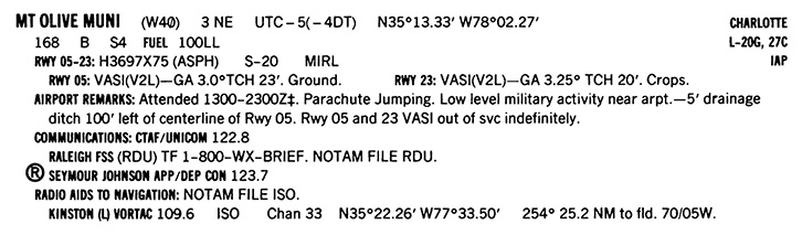
Figure 25-2 A sample airport entry in the Chart Supplement U.S.
Navigation Aids
VORs and VORTACs are prominently displayed on the en route charts, as they form the basis of the airways. Civil pilots use the VOR for course guidance, and the DME function of the TACAN for distance information. Many VORs transmit HIWAS messages (hazardous in-flight weather advisory service). NDBs are also depicted if they provide an en route function or transmit HIWAS messages.
Localizer front courses and/or back courses are only shown on FAA en route charts if, as well as providing approach guidance to an airport, they also serve an additional ATC function such as defining an intersection, and are therefore part of the en route structure. The same applies to LDAs and SDFs.
Routes
Airways, also known as federal airways, are controlled airspace established in the form of a corridor, the centerline of which is defined by navigation aids, usually VORTACs.
Below 18,000 feet MSL, the airways are known as VOR, or Victor airways, and are labeled with a “V” and their designated number, “V223.” They exist down to 1,200 feet AGL (higher in some instances), and are depicted on the low altitude en route charts. Various information is shown along the airways, such as the magnetic course, distance, MEA and MOCA. All distances are in nautical miles, and all directions are in degrees magnetic.
T-routes are depicted on en route low altitude charts and are available for use by RNAV-equipped aircraft from 1,200 feet above the surface (or in some instances higher), up to but not including 18,000 feet MSL. Q-routes are depicted on en route high altitude charts and are available for use by RNAV-equipped aircraft between 18,000 feet MSL and FL 450 inclusive. These relatively new types of airways can be defined by GPS waypoints and require an IFR-capable GPS receiver.
Breaks in airways are shown at intersections (published fixes) by a triangle, and at mileage break points not coincident with an intersection by a small cross. DME distance to the relevant VORTAC is shown at intersections, if appropriate.
A segment of an airway common to more than one route carries the numbers of each of these routes, “V107-301,” but you only need to indicate the number of the route you are using on your flight plan, “V301.” Alternate airways are identified by their location with respect to the associated main airway, “V12W” is to the west of “V12.”
From 18,000 feet MSL up to and including FL 600, the airspace is Class A. Flight in Class A airspace is IFR only, and the airways from 18,000 feet MSL up to and including FL 450, are known as jet routes. These are labeled with a “J” and their designated number, “J84.” The low altitude en route charts are not designed for flights above 18,000 feet MSL.
Minimum En Route IFR Altitude (MEA)
The MEA appears as a number, such as 9,500, along the airway and is the lowest published altitude between fixes that assures:
- acceptable navigation signal coverage (but not necessarily 2-way communications coverage); and
- meets obstacle clearance requirements between those fixes (1,000 feet normally, 2,000 feet in designated mountainous areas) within ±4 NM of the route to be flown.
It is usual to maintain an IFR altitude at or above the MEA that is in accordance with the hemispherical rule (WEEO: West-evens, East-odds), determined by your magnetic course (not heading). Occasionally, an MEA may be approved with a gap in navigation signal coverage, and this will be depicted on FAA charts with the words “MEA GAP,” and on Jeppesen charts by a broken bar. Some routes have directional MEAs, the MEA depending on which direction you are traveling — the MEA flying toward high ground being higher than when flying in the opposite direction away from high ground.
A bar crossing an airway at an intersection indicates that there is a change of MEA. You do not have to commence a climb to a higher MEA until reaching the intersection where the MEA change occurs, unless a minimum crossing altitude (MCA) is specified.
Minimum Crossing Altitude (MCA)
The MCA is the lowest altitude at certain fixes at which an aircraft may cross when proceeding in the direction of a higher MEA. The MCA is usually specified for obstacle clearance requirements, but it may also be specified to assure adequate reception of navigation signals so that you can identify the intersection. MCA is indicated by a “flagged X” on FAA charts, and as an airway number and altitude alongside the intersection on Jeppesen charts (“V-25 11000S” means MCA 11,000 feet MSL flying south on V-25).
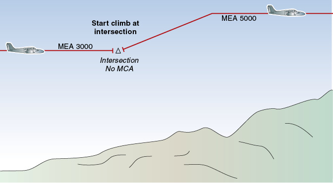
Figure 25-3 Approaching a higher MEA, with no MCA specified.
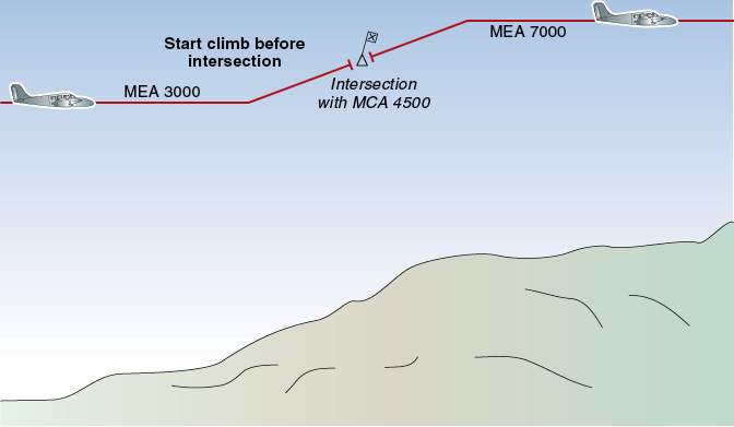
Figure 25-4 Approaching a higher MEA, with an MCA specified for the following course.
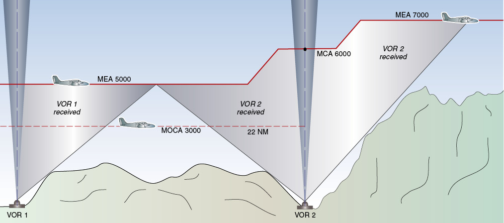
Figure 25-5 MEA, MOCA and MCA.
Minimum Obstruction Clearance Altitude (MOCA)
The MOCA is the lowest published altitude in effect between fixes on VOR airways, off-airway routes, or route segments which meets obstacle clearance requirements for the entire route segment, and which ensures acceptable navigation signal coverage only within 22 nautical miles (25 statute miles) of a VOR. The MOCA, if shown, is differentiated from the MEA by an asterisk on FAA charts (*2500), and a “T” on Jeppesen charts (2500T). If the MOCA is the same as the MEA, it is not shown.
Minimum Reception Altitude (MRA)
The MRA is the lowest altitude at which an intersection can be determined. At altitudes lower than the MRA, navigation signal coverage is not assured, and you may not be able to identify the intersection. An MRA is indicated by a “flagged R” on FAA charts, and by “MRA” on Jeppesen charts (MRA 9000).
Changeover Points (COPs)
A changeover point (COP) is the position en route between two adjacent navigation facilities where changeover in navigation guidance should occur, from the ground station behind to the ground station ahead. If the COP is not at the midway point, then it will be shown on aeronautical charts with the appropriate DME distances. COPs are designed to prevent the loss of navigation guidance, to prevent frequency interference from other ground facilities, and to prevent use of different facilities by other aircraft that are operating in the same airspace. You should use COPs to the fullest extent.
Maximum Authorized Altitude (MAA)
The MAA is the highest usable altitude for an airspace structure or route segment at which adequate reception of navigation signals is assured. At altitudes above the MAA, there may be navigation signal interference from another station on the same frequency. It is rare to see an MAA on a chart.
Note. Sample excerpts of FAA low-altitude En Route IFR Charts are given in figures 25-6 and 25-7.
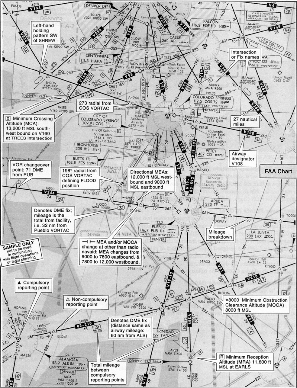
Figure 25-6 FAA En Route IFR Chart — route structure.
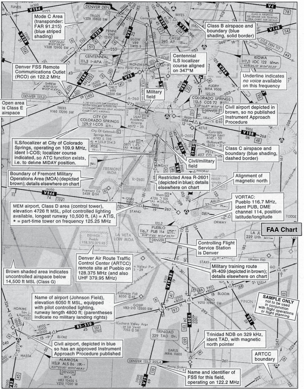
Figure 25-7 FAA En Route IFR Chart — facilities and airspace structure.
Airspace
U.S. airspace is organized into six classes (A, B, C, D, E and G), in line with International Civil Aviation Organization (ICAO) standards. Classes A through Class E are allocated to controlled airspace — Class A being the most restrictive and Class E for general controlled airspace. Uncontrolled airspace is allocated Class G. (Class F, although available in the ICAO system, has not been allocated in the U.S.)
The airspace classification system links various parameters to each airspace class, including:
- entry requirements (for example, radio contact for all aircraft in Class C airspace; ATC clearance for IFR flights in controlled airspace);
- minimum pilot qualifications;
- two-way communication and transponder equipment requirements;
- VFR weather minimums (where VFR is available — Classes B, C, D, E and G); and
- aircraft separation, conflict resolution and traffic advisory services.
Subdivision of Airspace
The structure of U.S. airspace is as follows:
Class A. Class A is generally that airspace extending from 18,000 feet MSL up to FL600: specified as IFR only.
Class B. Class B airspace extends from a surface area and attached stepped tiers, up to a designated altitude. This airspace is established at all major U.S. airports and requires the use of a Mode C transponder and prior ATC clearance for all flights, and an operable VOR for IFR flights.
Class C. Class C airspace extends from a surface area of 5 NM radius, usually with one stepped tier of 10 NM radius at 1,200 feet AGL, up to a designated altitude (usually 4,000 feet HAA, expressed as MSL). This airspace is established at designated airports where ATC provides radar vectoring and sequencing on a full-time basis for all IFR and VFR traffic.
Class D. Class D is airspace surrounding any other tower-operated airport, extending from a surface area up to 2,500 feet AGL (expressed as an MSL altitude). Areas are normally cylindrical in shape, plus any extensions up to 2 NM that are necessary to include and protect any instrument approach and departure paths. Extensions stretching more than 2 NM from the Class D “core” area become all Class E airspace.
Class E. Class E is allocated to general controlled airspace. This includes airports without control towers, transition areas (upward from 700 feet AGL at airports with published instrument approaches, and upward from 1,200 feet AGL when associated with airway route structures or segments) designed to contain IFR operations within controlled airspace when transiting between the terminal and en route environments; federal airways; plus all unallocated airspace over the U.S. from 14,500 feet MSL up to the Class A area commencing at 18,000 feet MSL.
Class G. Class G is allocated to all remaining airspace, which is uncontrolled.
Note. Special-use airspace is not allocated a class.
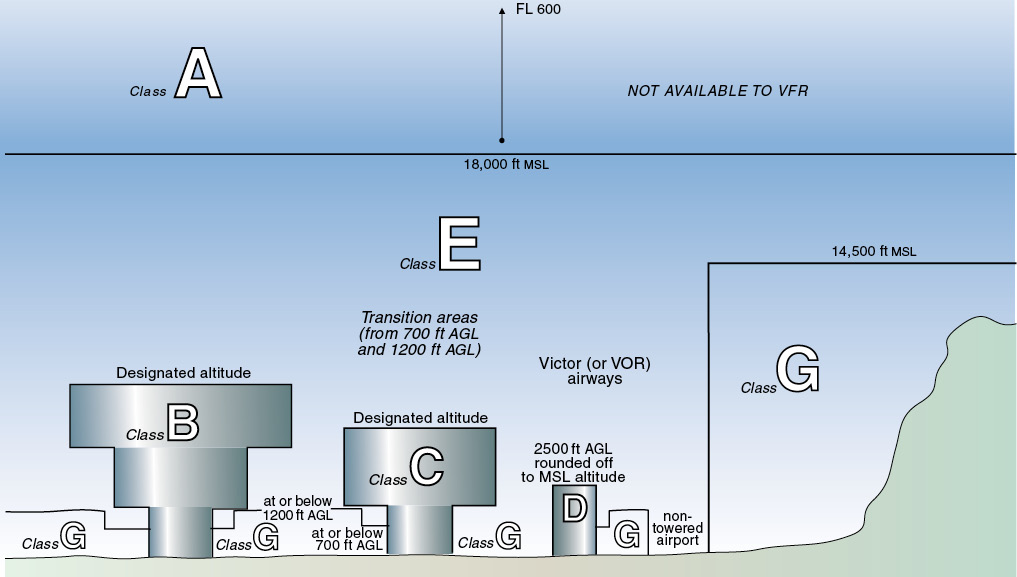
Figure 25-8 Summary of U.S. airspace classifications.
|
Airspace Features |
Class A Airspace |
Class B Airspace |
Class C Airspace |
Class D Airspace |
Class E Airspace |
Class G Airspace |
|
Flight operations permitted |
IFR |
IFR and VFR |
IFR and VFR |
IFR and VFR |
IFR and VFR |
IFR and VFR |
|
Entry prerequisites |
ATC clearance |
ATC clearance |
IFR clearance/VFR radio contact |
IFR clearance VFR radio contact |
Clearance/radio contact for IFR |
None |
|
Minimum pilot qualifications |
Instrument rating |
Private Pilot Cert./*endorsed student |
Student Certificate |
Student Certificate |
Student Certificate |
Student Certificate |
|
Two-way radio comms |
Yes |
Yes |
Yes |
Yes |
IFR |
No |
|
VFR minimum visibility |
not applicable |
3 statute miles |
3 statute miles |
3 statute miles |
**3 statute miles |
***1 statute mile |
|
Aircraft separation |
All |
All |
IFR, SVFR and runway operations |
IFR, SVFR and runway operations |
IFR, SVFR |
None |
|
Conflict resolution (collision avoidance) |
not applicable |
not applicable |
Between IFR and VFR flights |
No |
No |
No |
|
Traffic advisories |
not applicable |
not applicable |
Yes |
Workload permitting |
Workload permitting |
Workload permitting |
|
Safety advisories |
Yes |
Yes |
Yes |
Yes |
Yes |
Yes |
|
* Operations at some Class B airports require a minimum of a Private Pilot Certificate — see 14 CFR 91. ** Visibility and cloud clearance requirements increase above 10,000 feet MSL. *** Visibility and cloud clearance requirements decrease below 1,200 feet AGL;increase above 10,000 feet MSL, and at night — see 14 CFR 91 or AIM 3. |
||||||
|
Table 25-1 Summary of the U.S. airspace classification system. |
||||||
Maximum Aircraft Speeds
- Maximum 250 KIAS below 10,000 feet MSL (unless ATC authorizes otherwise in Class A or B airspace).
- Maximum 200 KIAS within 4 NM of the primary airport of a Class C or D airspace area (unless ATC authorizes or requires otherwise).
- Maximum 200 KIAS in the airspace underlying a Class B area designated for an airport, or in a VFR corridor through Class B airspace.
- Federal regulations do not allow civilian aircraft to enter into supersonic flight over the U.S.
Note. Some airports offer radar advisory services known as terminal radar service areas (TRSAs). The primary airport of a TRSA is Class D airspace, with the remaining portion usually overlying Class E (transition) airspace.
Airspace Depiction on Low-Altitude En Route Charts
FAA low-altitude en route charts show all airspace up to, but not including, 18,000 feet MSL.
- Class B areas — light-blue shading with a solid-blue border line;
- Class C areas — similar light-blue shading, but with a dashed-blue border line;
- Class C and Class D airports (the appropriate letter placed inside a box);
- Class E airspace is shown as open white space;
- Class G airspace (uncontrolled airspace, below 14,500 feet MSL) is shown as brown shaded areas;
- Mode C areas (encoding altimeter mandatory) — striped blue tint lines; and
- Special-use airspace — blue or brown hatched lines (prohibited areas, restricted areas, military operations areas [MOAs]). Military training routes, alert areas, and controlled firing areas are also delineated (use a chart legend for details).
Jeppesen Low-Altitude en route Charts show airspace classifications with the appropriate letter in parentheses: (B), (C), and (D).
Flight Plan and ATC Clearance
IFR flights must submit a full flight plan and receive an air traffic clearance for all operations within controlled airspace — Classes A through E. The flight plan should be submitted at least 30 minutes prior to the estimated time of departure (ETD). The procedure is covered in more detail later in the chapter.
Communications
FSS communications frequencies are shown on en route charts near NAVAID boxes, 122.45 on FAA, and 2.45 on Jeppesen (the initial 12 of the 122.45 not being shown because it is always 12). The standard FSS frequency is 122.2 MHz. You normally transmit and receive on the one COM frequency.
There are some frequencies, however, that you can contact FSS on, but they cannot reply. These frequencies are labeled R on FAA (for FSS receive only), and G on Jeppesen (for FSS guarded), 122.1R (FAA), 2.1G (Jeppesen). FSS will reply to you on the associated VOR frequency, 110.0 MHz. Therefore, when using this method of radio communication, you would select COM to 122.1 on which to transmit, and select the NAV to 110.0 with the audio ON to hear the response from FSS.
The emergency frequency 121.5 MHz is available at almost all FSS’s, and is not shown on the charts. This is one frequency that you should remember. It is used internationally.
Remote communications outlets (RCOs) are unmanned communications facilities, remotely controlled by ATC personnel, used to extend communication to pilots operating well away from direct or line-of-sight radio coverage. RCOs allow communications at some remote satellite airports (for the issuance of clearances, closing flight plans, etc.) and, as a secondary function, are used for advisory purposes when the aircraft is below coverage of the primary air/ground frequency. They are labeled RCO on FAA charts, with the controlling FSS beneath, and associated with the airport data on Jeppesen charts, with the controlling FSS above.
Note. Some limited remote communications facilities are not equipped with the emergency frequency 121.5 MHz. Also, some RCOs are used to control pilot-controlled lighting.
The boundary of an ARTCC (Center) area of responsibility is shown by a ragged line (FAA) or dotted line (Jeppesen) across the en route chart, with the appropriate Center name either side of the line. The Center frequencies are shown in boxes (ragged or dotted) in various places in the appropriate areas.
The common traffic advisory frequency (CTAF), used for traffic advisory purposes at an airport without an operating control tower, is found in the Chart Supplement U.S., and on DP and IAP charts. The CTAF frequency may be a UNICOM, MULTICOM, FSS or tower frequency. UNICOM is a non-government frequency.
Flight Planning
The most current departure, en route, and destination flight information should be obtained from the FSS when planning an IFR flight. You should obtain a thorough and legal weather briefing. Select the most suitable route to your destination, using the en route charts, and check for nonstandard takeoff minimums, special IFR departures and DPs at the departure airport, STARs and instrument approach procedures at the destination and alternate airports. Check the Chart Supplement U.S. for further information on the airports. Confirm that takeoff and landing distances are adequate.
Check NOTAMs. NOTAM information is classified into four categories:
- NOTAM (D) or distant — information which is disseminated for all navigational facilities that are part of the National Airspace System (NAS), all public use airports, seaplane bases, and heliports listed in the Chart Supplement U.S. NOTAM (D) information includes such data as taxiway closures, personnel and equipment near or crossing runways, and airport lighting aids that do not affect instrument approach criteria, such as VASI.
- Flight Data Center (FDC) NOTAMs — information that is regulatory in nature. FDC NOTAMs contain such things as amendments to published IAPs and other current aeronautical charts. They are also used to advertise temporary flight restrictions caused by, for example, natural disasters, or large-scale public events that may generate air traffic congestion over a site.
- Pointer NOTAMs — issued by a flight service station to highlight or point out another NOTAM, such as an FDC NOTAM or NOTAM (D). This type of NOTAM will assist users in cross-referencing important information that might not be found under an airport or NAVAID identifier.
- Military NOTAMs — these pertain to U.S. Air Force, Army, Marine, and Navy navigational aids/airports that are part of the NAS.
NOTAMs are given in either:
- Service A distribution via telecommunications if the information is time critical —you will receive these along with your weather briefing; or
- Notices to Airmen Publication (NTAP), which is published every four weeks. Data is included in this publication to reduce congestion on the telecommunications circuits. Once published in the NTAP, the information is not provided during pilot weather briefings unless specifically requested by the pilot.
Preferred IFR Routes
Preferred IFR routes have been established between busier airports to facilitate traffic flow. IFR clearances are generally issued on the basis of these routes, unless severe weather or some other reason dictates otherwise.
Preferred IFR routes are listed in the Chart Supplement U.S., and in the Jeppesen airway manual. For instance, the preferred IFR route from Houston-Hobby airport to New Orleans is: “V198 TBD V552.” This means: out of Houston on V198 to TBD VORTAC and then along V552 to New Orleans. Shorthand is sometimes used: “TBD093101” means track out on the TBD 093 radial to 101 DME.
Routing between particular airports and fixes on preferred IFR routes is often via DPs and STARs, or radar vectors.
Tower En Route Control (TEC) Routes
TEC routes link approach control areas between certain city pairs, allowing the flight to be completed using tower communications (approach/departure) only. TEC is designed for short low-level flights in a busy traffic environment. You may request it by writing TEC in the remarks section of your flight plan. Tower en route clearances are available in many places without filing a flight plan, simply by calling clearance delivery and requesting a tower en route clearance.
Shortest Route via Airways
To facilitate Air Traffic Control, you should file via airways or jet routes established for your planned altitudes or flight levels, and describe the route on your flight plan using the published type-number designators, such as “V262” for airway Victor 262, or “J5” for jet route 5.
If you plan to use more than one airway or jet route, clearly indicate the point of transition, which will usually be a VORTAC or waypoint. For instance, the route: “V27 MQO V113” indicates that you will fly along airway Victor 27 until the point MQO (Morro Bay VORTAC) where you will turn to Victor 113.
After takeoff from some airports, you can join the airway via a departure procedure (DP), and then leave an airway for an approach into the destination airport via a standard terminal arrival (STAR). For instance, the route: “SBA HABUT 2 GVO V27 MQO V113 PRB” indicates: from SBA (Santa Barbara) airport via the HABUT 2 DP to the point GVO (Gaviota) where airway Victor 27 will be joined and followed to MQO (Morro Bay) VORTAC, from where Victor 113 will be followed to PRB (Paso Robles).
Direct route segments not along airways can be defined by fixes. For instance, “GVO FLW” indicates from Gaviota direct to Fellows.
Direct Routes
For off-airways navigation, for instance using area nav (RNAV) or IFR-approved GPS equipment, calculation of a safety altitude is important, since terrain and other obstacles may not be seen in IFR conditions.
Jeppesen low en route charts depict minimum off route altitude (MORA) for each grid quadrant. FAA charts use off route obstacle clearance altitude (OROCA). These altitudes ensure that you will have 2,000 feet of terrain clearance in mountainous areas and 1,000 feet in non-mountainous regions out to 4 NM outside of the grid. This means you can fly your own off-airways route using the MORA and be assured of terrain clearance. In addition, you can fly lower than the MORA in a particular grid as long as you use a VFR sectional to ensure that you have at least 2,000 feet of clearance (mountainous) or 1,000 feet (non-mountainous). Remember, the MORA assures you of adequate clearance from the highest object in that grid. You can plot a course lower than that, but you need to select an altitude based on the contour lines of the VFR chart. You will also need to ensure that service volumes for VORs that define the route provide adequate signal coverage. For instance, below 14,500 feet two H class VORs should be within 80 miles of each other. See figure 12-9. Also, check the Chart Supplement U.S. for unusable VOR radials.
Selection of Altitude
Consider the en route winds and weather, and select an altitude that is:
1. an IFR altitude (WEEO);
2. at or above the MEA; and
3. with favorable winds, and preferably not in icing conditions.
Alternate Airports
Apply the ETA ±1 – 2 – 3 rule to your destination airport to see if it requires an alternate. For the period 1 hour either side of your destination ETA, the ceiling and visibility must be at least 2,000 feet/3 SM for there to be no need for an alternate. To be suitable as an alternate, the alternate airport forecast must be at your estimated time of arrival:
- at least the alternate minimums as published for that airport (in the front of the applicable IAP booklet, and on Jeppesen IAP charts); otherwise
- ceiling 600 feet, visibility 2 SM, if it has a precision approach;
- ceiling 800 feet, visibility 2 SM, if it has a nonprecision approach.
When you actually arrive at the alternate after diverting, whether you may land or not depends on the landing minimums, not the alternate minimums.
Fuel Requirements
Fuel requirements should be calculated carefully, with consideration being given to arrival at an alternate airport with adequate reserves still remaining. Being low on fuel increases pilot stress if a diversion becomes necessary.
The minimum fuel requirements for an IFR flight are for:
- departure to destination; plus
- destination to alternate (if required); plus
- 45 minutes fuel reserve calculated at normal cruise rate.
In the absence of more specific figures, you should allow approximately 15 minutes for each takeoff and departure, missed approach, and approach and landing. Any extra fuel in excess of the above requirements is available for holding.
The Flight Plan
To operate in controlled airspace (Classes A–E) under IFR, you are required to:
- file an IFR flight plan (usually done in person or by telephone to FSS or ATC on the ground at least 30 minutes prior to the flight); and
- obtain an air traffic clearance (usually requested by radio immediately prior to departure or entering controlled airspace).
The 30 minutes is required to allow time for ATC to process your flight data and (hopefully) avoid delays to your flight. The preferred methods of filing a flight plan are: in person by telephone or by DUATs — by radio is permitted, but discouraged because of the time it takes. Closing a flight plan by radio is typical because it takes just a few seconds.
Closing an IFR flight plan is automatically done by ATC at tower-controlled airports after landing. At an airport without an active control tower, you must close the flight plan with Flight Service or ATC by radio or telephone. Do this within 30 minutes of the latest advised ETA, otherwise search and rescue (SAR) procedures will begin.
- An IFR flight plan is required in both IMC and VMC in Class A airspace, and in IMC conditions in Classes B, C, D and E (controlled) airspace (and also in VMC, if you want to practice);
- An IFR flight plan is not required in Class G (uncontrolled) airspace.
To assist you in completing the flight plan and performing the flight, you should compile a navigation log, calculating time intervals and fuel requirements. To accomplish this you will need to gather all available information including enroute charts and determine any departure procedures or standard terminal arrival routes. A typical navigation log is shown in figure 25-9, and a typical flight plan form is shown in figure 25-10.
Important navigation log items to be inserted on the flight plan include:
- the planned route;
- the initial cruise altitude or flight level (later altitudes or flight levels can be requested in flight);
- the estimated time en route (ETE), in hours and minutes, from departure to touchdown at the first point of intended landing;
- the total usable fuel on board at takeoff, converted to endurance in hours and minutes.
AIM Chapter 5 provides a description of filling out an International Flight Plan form.
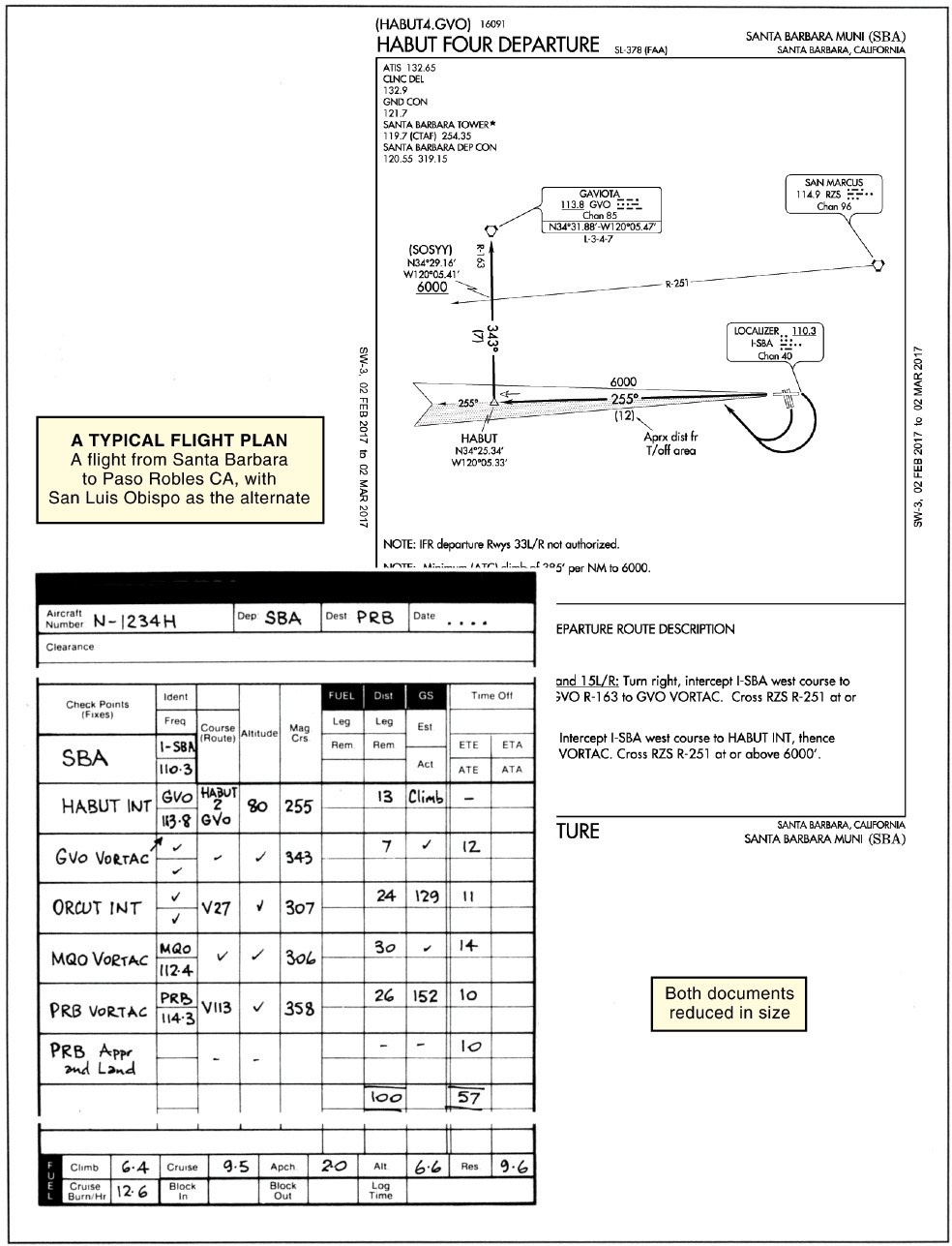
Figure 25-9 The Santa Barbara Habut 2 (DP) and a pilot’s navigation log.
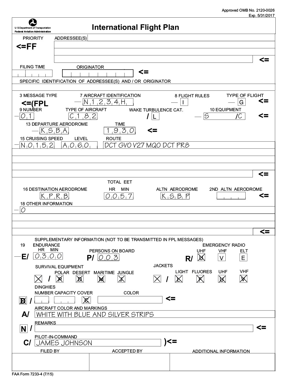
Figure 25-10 A typical ICAO flight plan form.
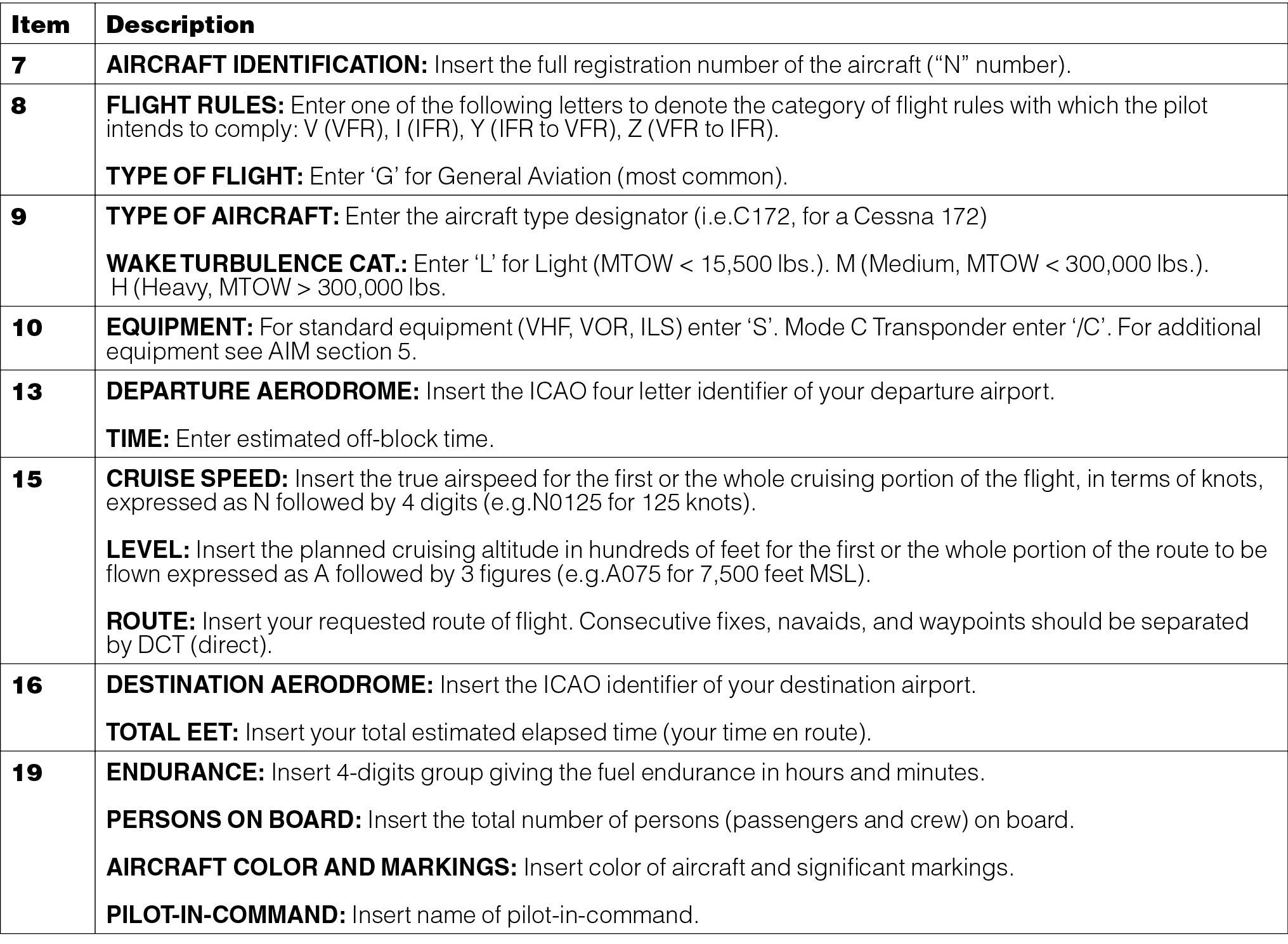
Table 25-2 Description of IFR flight plan ICAO.
Review 25
Preparation for Flight
En Route Charts (a)
1. What do the letters MEA stand for?
2. Does the MEA between two fixes meet obstacle clearance requirements between the two fixes?
3. Does the MEA between two fixes guarantee adequate navigation signal coverage between the two fixes?
4. Does the MEA between two fixes guarantee two-way radio communications when flying between the two fixes?
5. Does the MEA between two fixes guarantee radar coverage between the two fixes?
6. Does the MEA between two fixes guarantee DME reception between the two fixes?
7. Does the MEA between two fixes guarantee reception of more than one navigation signal at all points between the two fixes?
8. What is MOCA an abbreviation for?
9. Does the MOCA between two fixes meet obstacle clearance requirements between the two fixes?
10. Does the MOCA between two fixes guarantee adequate navigation signal coverage between the two fixes?
11. What distance from the VOR is an acceptable navigation signal coverage at the MOCA assured to?
12. Is the MOCA higher than the MEA?
13. Reception of signals from an off-airway facility when flying at the MEA may be inadequate to identify a fix or intersection. What is the minimum altitude at which the reception will be adequate known as?
14. You are cruising at the MEA of 7,000 feet MSL and have 30 NM to reach a radio fix beyond which the MEA is 8,500 feet MSL. If no MCA is specified, what is the lowest altitude at which you may cross the fix? The airplane is capable of a 500 fpm climb. When should this be initiated at the latest?
15. In the case of operations within a designated mountainous area, where no other minimum altitude is specified, what is the lowest altitude above the highest obstacle that an aircraft under IFR may be operated? What horizontal distance from the course flown is this within?
16. Does the MEA assure acceptable navigation signal coverage? Does it meet obstruction clearance requirements?
17. If no COP is shown on an en route chart for an airway between two VORTACs, where would you change VOR frequencies?
18. If the COP is not at the midway point between two VORs, how is it shown on the en route charts?
19. What is a waypoint?
20. Are Victor airways depicted on en route low-altitude charts?
21. Where does Class A airspace begin? Is it depicted on en route low-altitude charts?
22. What is the maximum speed below 10,000 feet MSL?
23. What is the maximum speed within 4 NM of the primary airport of a Class C airspace area?
24. Is special-use airspace depicted on en route low-altitude charts?
25. Which class of airspace includes extensions to Class D airspace which accommodate an instrument approach, and which extend more than 2 NM from the Class D core area?
26. Where do transition area extensions commence when associated with an airport with an instrument approach procedure in a Class D airspace area?
27. Where do transition areas associated with the airways route structure commence? Where do they extend up to?
28. What sort of airspace lies beneath a transition area and down to the surface?
29. What areas are established to separate certain military activities from IFR traffic?
30. What class of airspace is represented by unshaded white areas on FAA low-altitude en route charts?
31. Is ATC responsible for the control of air traffic in Class G airspace?
32. When is a mode-C equipped transponder required?
33. When is DME required to plan for flight?
34. How many stepped tiers does Class C airspace usually have? Where does Class C airspace extend upward to?
35. How is Class D airspace at an airport indicated? What altitude does Class D airspace usually extend upward to?
36. What is the minimum equipment required for flight within Class B airspace?
37. You are inbound and close your IFR flight plan 10 miles from your destination, which is a Class D towered airport. When should you be in contact with the control tower?
38. If the control tower is not operating, but there is an FSS at the airport, what sort of service will you receive?
39. Where can hours of operation of a control tower be found?
40. Can the time difference between local time and UTC at a particular airport be found in the Chart Supplement U.S.?
En Route Charts (b)
41. Are LDA approaches indicated on en route charts?
42. What communications frequencies are normally available at all FSS’s but are not shown above the Air/Ground communication boxes on FAA en route charts?
43. What does HIWAS stand for?
44. What do the areas shaded light brown on FAA low altitude en route charts denote?
Refer to figure 25-11 for questions 45 to 65.
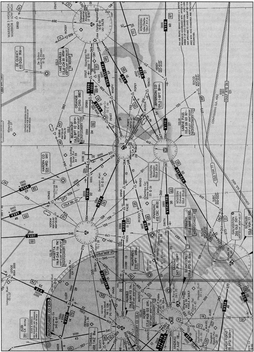
Figure 25-11 L-17 FAA low-altitude en route chart — excerpt of Galveston, Texas area (reduced in size).
45. Where is the VOR changeover point when flying east on V306 from Daisetta to Lake Charles?
46. What is the appropriate FSS to communicate within the Lake Charles area?
47. On which frequencies can you receive De Ridder FSS during the day in the Lake Charles area?
48. What is the appropriate FSS to communicate with over the Daisetta VOR?
49. Can you talk to, and receive messages from, Montgomery County FSS on 122.1 in the Daisetta area?
50. How can you receive messages from Montgomery County FSS in reply to a call you have made on 122.1 in the Daisetta area?
51. What frequencies can you receive Montgomery County FSS on during the day in the Daisetta area?
52. What does the striped area around the Houston Class B airspace indicate?
53. At Jefferson County airport, why is the back course of the localizer depicted, but not the front course?
54. What airspace exists at Jefferson County airport?
55. Where is the VOR changeover point when flying southwest from Jefferson County along V20 to Hobby?
56. Where is the VOR changeover point when flying from Jefferson County along V20 to Hobby?
57. What is the MEA flying northwest from Jefferson County to Daisetta along V574?
58. What is the MEA flying north from Jefferson County to SILBE intersection along V569?
59. What is the MEA flying north from SILBE intersection along V569? Is adequate obstruction clearance assured at this altitude? Is adequate navigation signal coverage assured at this altitude?
60. What is the meaning of the symbol: “*1800” flying north from SILBE intersection along V569? Is adequate obstruction clearance assured at this altitude? Is adequate navigation signal coverage assured at this altitude?
61. What are the ARTCC frequencies in the Jefferson County and the Lake Charles areas?
62. Which frequency is the HIWAS available on in the area near Jefferson County airport? Which radio would you select for this?
63. What available lighting is indicated on the chart at Lake Charles Regional airport?
64. What is the responsible ARTCC unit and frequency in the Lake Charles area?
Flight Planning
65. Where is the most current en route and destination flight information for planning an IFR flight obtained from?
66. Where are changes in flight data, such as changes on IFR approach and en route charts, notified?
67. How is the latest status of a runway determined?
68. Refer to figure 25-11. You plan an IFR flight from Lake Charles Regional to Montgomery County airport via V306, with cruise TAS 180. An extract of the meteorological FD is:
FT 3000 6000 9000 12000 LCH 2115 2325+08 2335+02 2340–04
a. What is the elevation of Lake Charles Regional airport?
b. Using an average groundspeed of 140 knots, and a rate of climb of 650 fpm, what distance is needed to reach the cruise altitude of 8,000 feet?
c. The initial route out of LCH is V306–552. V552 goes from LCH to which VORTAC?
d. Which intersection is this via?
e. What does the MEA on V306 change to at this intersection?
f. What calibrated airspeed (CAS) must be used to maintain the filed TAS at the flight plan altitude of 8,000 feet?
g. What is the estimated time interval from OFERS to DAS using the wind entry nearest your planned altitude of 8,000 feet? (Magnetic variation at LCH is shown as 7E in the Chart Supplement U.S.)
h. What is the distance from OFERS intersection to the VOR changeover point?
i. What is the course and distance out of DAS to the turning point beside Montgomery County airport?
j. What is the highest MEA DAS to the turning point?
k. What is the MOCA from DAS to Cleep?
l. What is the MOCA from Cleep to the turning point?
69. How would you determine whether or not a destination requires an alternate?
70. How would you determine whether or not an alternate airport is suitable?
71. What are the fuel requirements for an IFR flight?
72. What is the highest altitude a westbound flight can normally plan on a Victor airway?
73. The wind and temperatures aloft forecast predicts a wind of 340° at 30 knots at 9,000 feet altitude in the area of your planned flight. If the average magnetic variation is 20° east and your planned TAS at 9,000 feet is 170 knots, determine the flight plan heading and groundspeed for the following magnetic courses:
a. MC 080.
b. MC 110.
c. MC 140.
d. MC 170.
e. MC 020.
f. MC 040.
74. What CAS would you need to fly to achieve a filed TAS of 180 knots if the OAT is +8°C at 8,000 feet?
75. What CAS would you need to fly to achieve a filed TAS of 158 knots if the OAT is 0°C at 8,000 feet?
Flight Plan Form
Refer to the sample flight plan form in figure 25-10 or your own copy for questions 76 to 81
76. Which box should you check for an IFR flight?
77. What should you indicate for the “Type of Flight” box?
78. What letters should you enter under Item 10 Equipment if your aircraft is equipped with standard equipment and a Mode C transponder?
79. For Item 9, Wake Turbulence Category, what entry should be made for an aircraft with a maximum takeoff weight of 16,000 pounds?
80. S/C under Item 10 reflects what?
81. For Item 15, how should consecutive fixes and NAVAIDs be separated when requesting your route?
82. In order to avoid cancellation of the flight plan, you should advise ATC of a delay that extends beyond what period of time?
83. An IFR flight plan and an ATC clearance are required for operations in which class or classes of airspace?
84. Is an IFR flight plan and clearance required to operate in Class G airspace if IMC exists?
85. Is an IFR flight plan required to enter Class E airspace from Class G airspace in IMC?
86. To avoid delays, how much time prior to the proposed time of departure should an IFR flight plan be submitted?
87. Will an IFR flight plan be automatically closed by ATC when you land at an airport with an operating control tower?
88. Will an IFR flight plan be automatically closed by ATC if you land at an airport without an operating control tower?
89. How long after the latest advised ETA will search and rescue procedures begin if a flight plan has not been closed?
90. In which class or classes of airspace can an IFR flight plan be closed in flight if VFR conditions exist?
91. When is an IFR flight plan and clearance required to fly in VFR conditions?