


Chapter 4
Navigation
Table of Contents
NAVAID ClassesDistance Measuring Equipment (DME)
VHF Omnidirectional Range (VOR)
Horizontal Situation Indicator (HSI)
Area Navigation (RNAV)
Instrument Landing System (ILS)
Global Positioning System (GPS)
NAVAID Classes
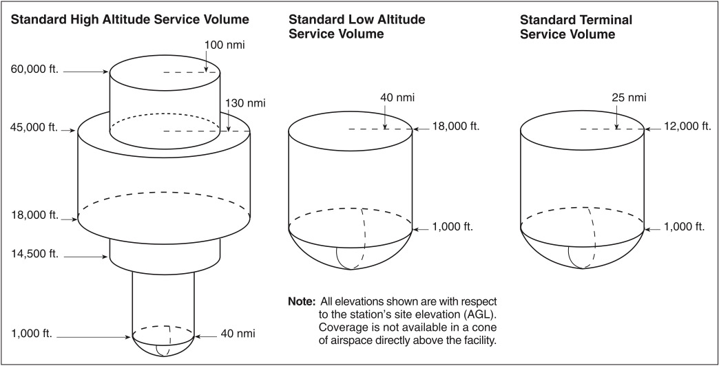
VOR and VORTAC facilities are classed according to their operational use. There are three classes:
1. T (Terminal).
2. L (Low altitude).
3. H (High altitude).
The class defines the service volume of the NAVAID (which is the reception limit to which an unrestricted NAVAID may be used for random or unpublished route navigation).
The service volume of VOR/VORTACs can be found in the Chart Supplements U.S. and in the AIM. The NAVAID class and any restrictions to use (unusable radials) will also be found in the Chart Supplements U.S. See Figure 4-1.
Distance Measuring Equipment (DME)
DME operates on the principle of a timed UHF signal that is transmitted from the aircraft to the ground station and back to the aircraft. This time is translated into a distance. The DME readout is presented in nautical miles (NM) and is slant range distance, not actual horizontal distance. When passing over a station, the range indicator will decrease until it indicates the height above the station. After crossing the station, it will start to increase. (If an aircraft passes over a station at 6,000 feet, the DME readout will be 1 NM.)
The greatest error in DME indications occur when an aircraft is very close to the station at a high altitude. The accuracy of the DME unit is valid only for 1 or more nautical miles from the ground facility for each 1,000 feet of altitude.
The identifier heard on the VORTAC or VOR-DME frequency is actually the identifiers of two separate radios on a time-shared basis. The DME portion identifies itself once every thirty seconds. The remaining identifiers are the VOR portion. Assuming both components are operating normally, there will be an uninterrupted series of identifiers.
VHF Omnidirectional Range (VOR)
VOR accuracy may be checked by means of a VOR Test Facility (VOT), ground or airborne checkpoints, or by checking dual VORs against each other. A VOT location and frequency can be found in the Chart Supplements U.S. To use the VOT, tune to the appropriate frequency and center the course deviation indicator (CDI). The omni-bearing selector (OBS) should read 0° with a FROM indication, or 180° with a TO indication. The allowable error is ±4°. VOR receiver checkpoints are listed in the Chart Supplements U.S. With the appropriate frequency tuned and the OBS set to the published certified radial, the CDI should center with a FROM indication when the aircraft is over the designated check point. Allowable accuracy is ±4° for a ground check, and ±6° for an airborne check. If the aircraft is equipped with dual VORs, they may be checked against each other. The maximum permissible variation when tuned to the same VOR is 4°.
The pilot must log the results of the VOR accuracy test in the aircraft logbook or other record. The log must include the date, place, bearing error, if any, and a signature.
All VOR stations transmit an identifier. It is a three-letter Morse code signal interrupted only by a voice identifier on some stations, or to allow the controlling flight service station to speak on the frequency. Absence of a VOR identifier indicates maintenance is being performed on the station and the signal may not be reliable.
All VOR receivers have at least the essential components shown in Figure 4-2.
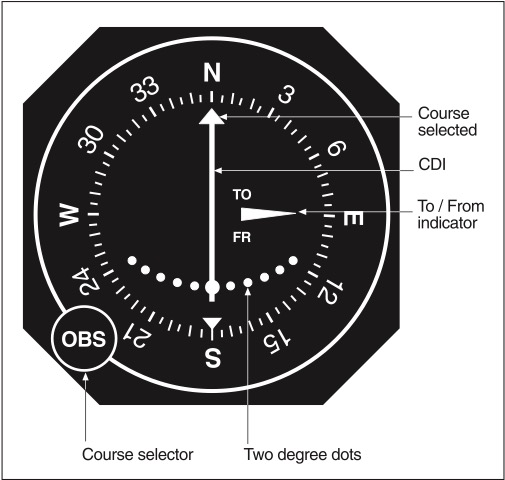
The pilot may select the desired course or radial by turning the OBS. The CDI centers when the aircraft is on the selected radial or its reciprocal. A full-scale deflection of the CDI from the center represents a deviation of approximately 10° to 12°. The TO/FROM Indicator (ambiguity indicator) shows whether the selected course will take the aircraft TO or FROM the station. A TO indication shows that the OBS selection is on the other side of the VOR station. A FROM indication shows that the OBS selection and the aircraft are on the same side of the VOR station. When an aircraft flies over a VOR, the TO/FROM indicator will reverse, indicating station passage.
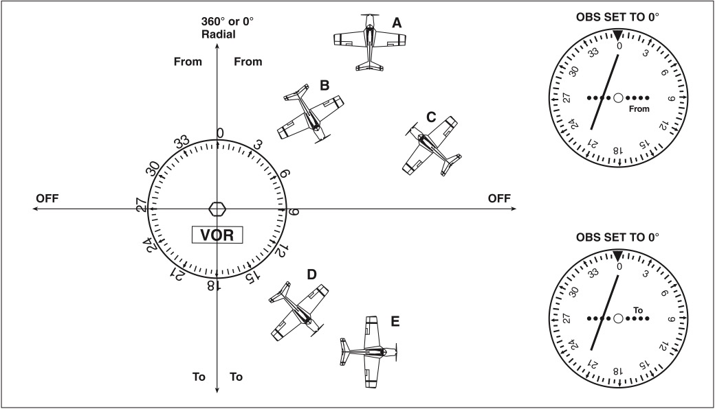
The position of the aircraft can always be determined by rotating the OBS until the CDI centers with a FROM indication. The course displayed indicates the radial FROM the station. The VOR indicator displays information as though the aircraft were going in the direction of the course selected. However, actual heading does not influence the display. See Figure 4-3.
VOR radials, all of which originate at the VOR antenna, diverge as they radiate outward. For example, while the 011° radial and the 012° radial both start at the same point, 1 NM from the antenna, they are 100 feet apart. When they are 2 NM from the antenna, they are 200 feet apart. So at 60 NM, the radials would be 1 NM (6,000 feet) apart. See Figure 4-4.
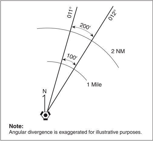
The VOR indicator uses a series of dots to indicate any deviation from the selected course, with each dot equal to approximately 2° of deviation. Thus, a one-dot deviation at a distance of 30 NM from the station would indicate that the aircraft was 1 NM from the selected radial (200 feet × 30 = 6,000 feet).
To orient where the aircraft is in relation to the VOR, first determine which radial is selected (look at the OBS setting). Next, determine whether the aircraft is flying to or away from the station (look at the TO/FROM indicator), to find which hemisphere the aircraft is in. Last, determine how far off course the aircraft is from the selected course (look at the CDI needle deflection) to find which quadrant the aircraft is in. Remember that aircraft heading does not affect orientation to the VOR.
Horizontal Situation Indicator (HSI)
The HSI is a combination of two instruments: the heading indicator and the VOR. See Figure 4-5.
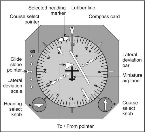
The aircraft heading displayed on the rotating azimuth card under the upper lubber line in Figure 4‑5 is 330°. The course indicating arrowhead that is shown is set to 300°. The tail of the course indicating arrow indicates the reciprocal, or 120°.
The course deviation bar operates with a VOR/LOC navigation receiver to indicate either left or right deviations from the course that is selected with the course indicating arrow. It moves left or right to indicate deviation from the centerline in the same manner that the angular movement of a conventional VOR/LOC needle indicates deviation from course.
The desired course is selected by rotating the course indicating arrow in relation to the azimuth card by means of the course set knob. This gives the pilot a pictorial presentation. The fixed aircraft symbol and the course deviation bar display the aircraft relative to the selected course as though the pilot was above the aircraft looking down.
The TO/FROM indicator is a triangular-shaped pointer. When this indicator points to the head of the course arrow, it indicates that the course selected, if properly intercepted and flown, will take the aircraft TO the selected facility, and vice versa.
The glide slope deviation pointer indicates the relationship of the aircraft to the glide slope. When the pointer is below the center position, the aircraft is above the glide slope and an increased rate of descent is required.
To orient where the aircraft is in relation to the facility, first determine which radial is selected (look at the arrowhead). Next, determine whether the aircraft is flying to or away from the station (look at the TO/FROM indicator) to find which hemisphere the aircraft is in. Next, determine how far from the selected course the aircraft is (look at the deviation bar) to find which quadrant the aircraft is in. Last, consider the aircraft heading (under the lubber line) to determine the aircraft’s position within the quadrant. Note that you will have reverse sensing if you’re flying the back course. You will know if you’re on the back course if the HSI is tuned to the reciprocal of where the localizer is positioned. For example, if the HSI is tuned to 090 but the localizer is on the 270 extension, then you are on the back course and will have reverse sensing.
Area Navigation (RNAV)
RNAV is a system of navigation which allows a pilot to fly a selected course without the need to overfly ground- or space-based navigation aids. To fly either an RNAV route or to execute an RNAV approach under IFR, the aircraft must have an approved RNAV receiver.
A waypoint is a predetermined geographical position used for route definition and/or progress reporting purposes.
Instrument Landing System (ILS)
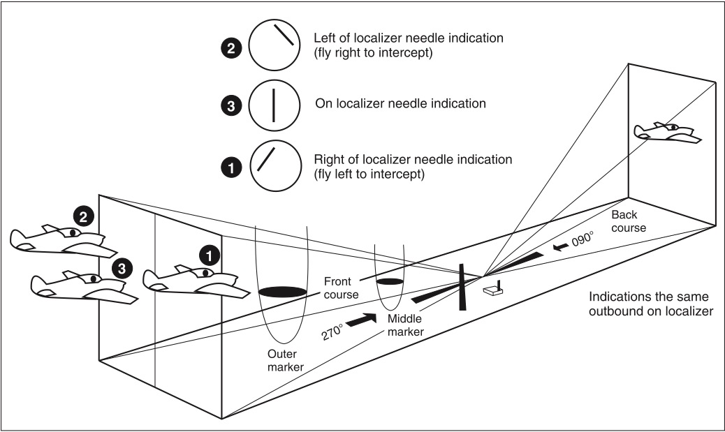
An ILS consists of a localizer, a glide slope, marker beacons, and approach lights. See Figure 4-6 and FAA CT-8080-3 Legend 38. The localizer provides azimuth information, furnishing the pilot with course guidance to the runway centerline. The approach course is called the front course and the localizer signal is transmitted from approximately 1,000 feet past the far end of the runway. At the runway threshold, the course width is adjusted to 700 feet. When tracking inbound on the localizer, drift corrections should be small and should be reduced as the course narrows. When the outer marker is reached, enough drift correction should be established so as to allow completion of the approach with heading corrections no greater than 2°. The localizer identification, which consists of a three-letter identifier preceded by the letter “I”, is transmitted in Morse code on the localizer frequency.
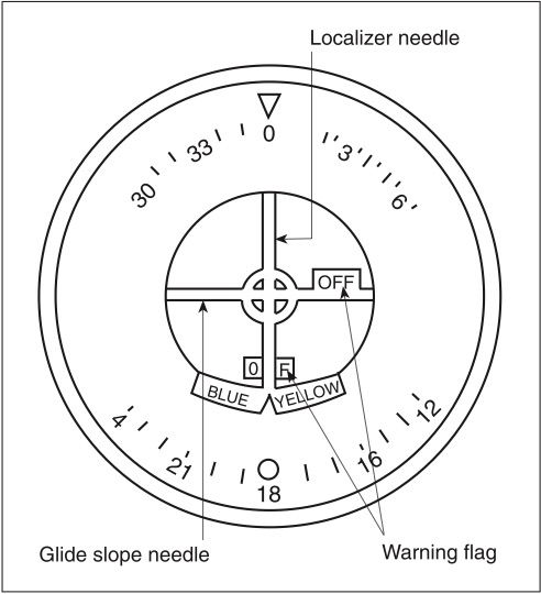
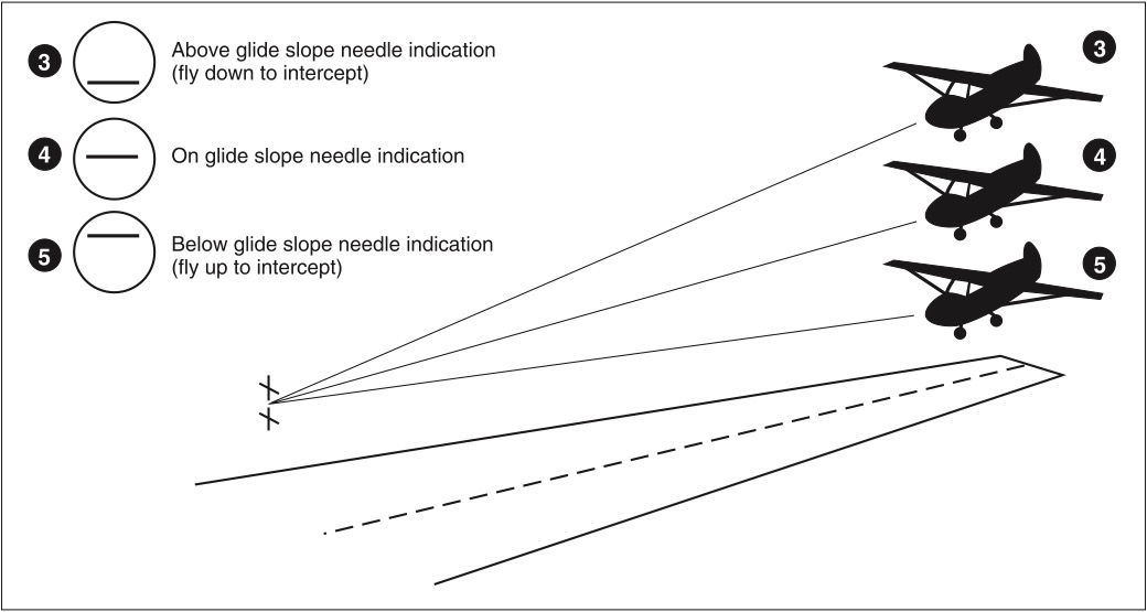
The glide slope transmitter is automatically tuned when the localizer frequency is selected. Offset from the runway approximately 1,000 feet from the approach end, it projects a beam 1.4° from full-scale. The glide slope angle is normally adjusted to 3° above horizontal so that it intersects the middle marker approximately 200 feet AGL, and is usable to a distance of about 10 NM. Figures 4-7 and 4-8 depict typical indications that a pilot would see during localizer and/or glide slope operations.
Low-powered transmitters called marker beacons are located along the ILS approach course. These beacons transmit their signals vertically upward in a very narrow beam across the localizer course. When an aircraft flies through the beam a receiver is activated which informs the pilot of the aircraft’s position relative to the runway. The marker beacon farthest from the runway is the outer marker (OM). Passing over the OM the pilot will hear a series of dashes, and a blue (or purple) light will illuminate on the instrument panel. Located 4 to 7 miles from the runway, the OM indicates a position at which an aircraft at the appropriate altitude on the localizer course will intercept the glide slope. Approximately 3,500 feet from the landing threshold, an aircraft on the glide slope will cross the middle marker (MM) at an altitude of approximately 200 feet. The pilot will hear alternating dots and dashes, and an amber light will illuminate on the instrument panel. At some locations, an inner marker (IM) is installed between the MM and the runway threshold. The IM is identified by dots transmitted at the rate of 4 per second and the illumination of a white light on the instrument panel. Frequently, low-powered nondirectional beacons called compass locators are co-located with outer and middle markers. For identification, a locator outer marker (LOM) transmits the first two letters of the localizer identification group, and the locator middle marker (LMM) transmits the last two letters of the localizer identifier.
A Localizer-Type Directional Aid (LDA) approach is of comparable utility and accuracy to a localizer. Like the localizer, it has a course width of approximately 5°, but it is not part of a complete ILS system and it is not aligned with the runway. It may have straight-in landing minimums.
The Simplified Directional Facility (SDF) provides a final approach course similar to that of the ILS localizer. It has no glide slope, and it may or may not be aligned with the runway. The course width will be fixed at either 6° or 12°, and the antenna may be offset from the runway centerline.
Global Positioning System (GPS)
GPS is a satellite-based radio navigational, positioning, and time transfer system. The GPS receiver verifies the integrity (usability) of the signals received from the GPS satellites through receiver autonomous integrity monitoring (RAIM) to determine if a satellite is providing corrupted information. Without RAIM capability, the pilot has no assurance of the accuracy of the GPS position. If RAIM is not available, another type of navigation and approach system must be used, another destination selected, or the trip delayed until RAIM is predicted to be available on arrival.
The database may not contain all of the transitions or departures from all runways and some GPS receivers do not contain DPs in the data base. It is necessary that helicopter procedures be flown at 70 knots or less since helicopter departure procedures and missed approaches use a 20:1 obstacle clearance surface (OCS), which is double the fixed-wing OCS, and turning areas are based on this speed as well. Any required alternate airport must have an approved instrument approach procedure other than GPS, which is anticipated to be operational and available at the estimated time of arrival and which the aircraft is equipped to fly.