


Chapter 9
Enroute Flight
Table of Contents
PilotageTime
Topography
Dead Reckoning
Plotting Courses
Magnetic Variation
Magnetic Deviation
Wind and Its Effects
The Wind Triangle
The Flight Computer (E6-B)
Finding Wind Correction Angle (WCA) and Ground Speed (GS)
Flight Computer Calculator Face
Finding Time, Rate, and Distance
Calculating Fuel Consumption
Finding True Airspeed and Density Altitude
Airspace
Pilotage
Air navigation is the art of directing an aircraft along a desired course and being able to determine its geographical position at any time. Such navigation may be accomplished by pilotage, dead reckoning, or using radio navigational aids.
Pilotage is the use of visible landmarks to maintain a desired course, and is the basic form of navigation for the beginning pilot operating under VFR. Visible landmarks which can be identified on aeronautical charts allow the pilot to proceed from one check point to the next.
The aeronautical charts most commonly used by VFR pilots are the VFR Sectional Aeronautical Chart, the VFR Terminal Area Chart, and the World Aeronautical Chart. All three charts include aeronautical information such as airports, airways, special use airspace, and other pertinent data.
The scale of the VFR Sectional Aeronautical Chart is 1:500,000 (1 inch = 6.86 NM). Designed for visual navigation of slow speed aircraft in VFR conditions, this chart portrays terrain relief and checkpoints such as populated places, roads, railroads, and other distinctive landmarks. These charts have the best detail and are revised every 6 months.
Information found on the VFR Terminal Area Chart is similar to that found on the VFR Sectional Chart, but the scale on this chart is 1:250,000 (1 inch = 3.43 NM). These charts are for a specific city with Class B airspace. They show much detail, but have small coverage.
The World Aeronautical Chart has a scale of 1:1,000,000, which is more convenient for use in navigation by moderate speed aircraft. It depicts cities, railroads, and distinctive landmarks, etc. These charts have less detail and are revised no more than once a year.
To identify a point on the surface of the earth, a geographic coordinate, or grid, system was devised. By reference to meridians of longitude and parallels of latitude, any position may be accurately located when using the grid system.
Equidistant from the poles is an imaginary circle called the equator. The lines running east and west, parallel to the equator are called parallels of latitude, and are used to measure angular distance north or south of the equator. From the equator to either pole is 90°, with 0° being at the equator; while 90° north latitude describes the location of the North Pole. See Figure 9-1.
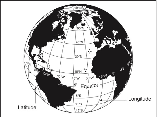
Lines called meridians of longitude are drawn from pole to pole at right angles to the equator. The prime meridian, used as the zero degree line, passes through Greenwich, England. From this line, measurements are made in degrees both easterly and westerly up to 180°.
Any specific geographical point can be located by reference to its longitude and latitude. For example, Washington, DC is approximately 39° north of the equator and 77° west of the prime meridian and would be stated as 39°N 77°W. Note that latitude is stated first.
In order to describe a location more precisely, each degree (°) is subdivided into 60 minutes (') and each minute further divided into 60 seconds ("), although seconds are not shown. Thus, the location of the airport at Elk City, Oklahoma is described as being at 35°25'55"N 99°23'15"W (35 degrees, 25 minutes, 55 seconds north latitude; 99 degrees, 23 minutes, 15 seconds west longitude). Degrees of west longitude increase from east to west. Degrees of north latitude increase from south to north.
Time
Time is measured in relation to the rotation of the earth. A day is defined as the time required for the earth to make one complete revolution of 360°. Since the day is divided into 24 hours, it follows that the earth revolves at the rate of 15° each hour. Thus, longitude may be expressed as either 90° or 6 hours west of Greenwich.
Twenty-four time zones have been established. Each time zone is 15° of longitude in width, with the first zone centered on the meridian of Greenwich. Each zone uses the local time of its central meridian as shown in FAA Figure 27.
For example, when the sun is above the 90th meridian, it is noon central standard time (CST). At the same time it is 6 p.m. Greenwich, 11 a.m. mountain standard time (MST), and 1 p.m. eastern standard time (EST). When daylight saving time (DST) is in effect, the sun is over the 75th meridian at noon CST.
Most aviation operations time is expressed in terms of the 24-hour clock, (for example, 8 a.m. is expressed as 0800; 2 p.m. is 1400; 11 p.m. is 2300) and may be either local or Coordinated Universal Time (UTC). UTC is the time at the prime meridian and is represented in aviation operations by the letter “Z,” referred to as Zulu time. For example, 1500Z would be read as “one five zero zero Zulu.”
In the United States, conversion from local time to UTC is made in accordance with the table in the lower left corner of FAA Figure 27.
Problem: An aircraft departs an airport in the Pacific standard time zone at 1030 PST for a 4-hour flight to an airport located in the central standard time zone. The landing should be at what coordinated universal time (UTC)?
Solution: Use the conversion table in FAA Figure 27 and the following steps:
1. Convert 1030 PST to UTC:
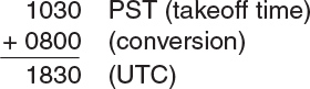
2. Add the flight time.
Topography
A VFR Sectional Aeronautical Chart is a pictorial representation of a portion of the Earth’s surface upon which lines and symbols in a variety of colors represent features and/or details that can be seen on the Earth’s surface. Contour lines, shaded relief, color tints, obstruction symbols, and maximum elevation figures are all used to show topographical information. Explanations and examples may be found in the chart legend. Pilots should become familiar with all of the information provided in each Sectional Chart Legend, found in FAA Legend 1.
Dead Reckoning
Dead reckoning is the method used for determining position with a heading indicator and calculations based on speed, elapsed time, and wind effect from a known position. The instruments used for dead reckoning navigation include the outside air temperature gauge, the airspeed indicator, the altimeter, the clock, and the magnetic compass system or slaved gyro system. These instruments provide information concerning direction, airspeed, altitude, and time, and must be correctly interpreted for successful navigation.
Plotting Courses
A course is the direction of flight measured in degrees clockwise from north. Meridians of longitude run from the south pole to the north pole. This alignment is called true north. When a course is plotted on a chart in relation to the lines of longitude and/or latitude it is called a true course (TC), and will be expressed in three digits. North may be either 360° or 000°; east is 090°; south is 180°; and west is 270°. Any attempt to project lines of latitude and longitude onto a flat surface such as a chart results in a certain amount of distortion. When plotting a course on a sectional aeronautical chart, this distortion may be minimized by measuring true course in reference to the meridian nearest to the halfway point between the departure point and the destination.
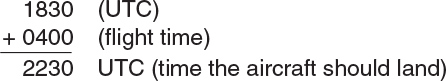
A common type of plotter that is used to plot a course is shown in Figure 9-2. This plotter is a semi-circular protractor with a straight edge attached to it. The straight edge has distance scales that match various charts and these scales may depict both statute and nautical miles. A small hole at the base of the protractor portion indicates the center of the arc of the angular scale. Two complete scales cover the outer edge of the protractor, and they are graduated in degrees. An inner scale measures the angle from the vertical.
To determine TC, use the plotter in the following manner:
1. Using the straight edge of the plotter as a guide, draw a line from the point of departure to the destination.
2. Place the top straight edge of the plotter parallel to the plotted course and move the plotter along the course line as necessary to place the small center hole over a meridian as near to the halfway point of the course as possible. See Figure 9-2a.
3. The TC is the angle measured between the meridian and the course line. See Figure 9-2b. The outer scale is used to read all angles between north through east to south, and the inner scale is used to read all angles between south through west to north. In Figure 9-2 the TC from point (a) to point (b) is 115° as read at point (c).
4. Course lines which fall within 30° of true north or south can be more easily measured by sliding the plotter along the course line until the hole falls over a horizontal latitude line; use the partial protractor scale for these measurements.
Magnetic Variation
The north pole where all meridians converge is true north. The north pole which attracts the needle of a compass is magnetic north. These two poles are not in the same place. At any point where magnetic north and true north are in line with each other, the compass needle points both to magnetic north, and coincidentally, true north. The line along which this occurs is known as the agonic line. When positioned west of the agonic line, a compass will point right (east) of true north. When positioned east of the agonic line, a compass will point left (west) of true north. This angular difference between true north and magnetic north is called magnetic variation (VAR). West of the agonic line, variation is “easterly.” East of the agonic line, variation is “westerly.”
The amount and direction of variation is depicted on sectional charts as dashed magenta colored lines connecting points of equal variation, called isogonic lines.
A course measured on a sectional chart is a true course: it is measured from a meridian, which runs from the south pole to the north pole. Since a magnetic compass is used to maintain a course while flying, this TC must now be converted to a magnetic course (MC). This conversion is made by either adding or subtracting the variation. To convert a TC to an MC, subtract easterly variation and add westerly variation: “East is least, west is best.”
TC ± VAR = MC
Magnetic Deviation
The magnetic compass is affected by influences within the aircraft such as electrical circuits, radios, engines, magnetized metal parts, etc., which cause the compass needle to be deflected from its normal reading. This deflection is known as deviation (DEV), and it must be applied to convert a magnetic course to a compass course (CC) to make it usable in flight.
Deviation, which is different for each aircraft, may also vary for different courses in the same airplane. To let the pilot know the appropriate correction, a correction card is mounted near the compass.
To determine the actual compass reading to be followed during flight, it is necessary to apply the corrections for both variation and deviation:
True Course ± Variation = Magnetic Course ± Deviation = Compass Course
or,
TC ± VAR = MC ± DEV = CC.
Wind and Its Effects
An additional computation, common to both pilotage and dead reckoning, is necessary to compensate for the effect of wind.
Wind direction is reported as the direction from which the wind blows, i.e., wind blowing from the west to the east is a west wind. Wind speed is the rate of motion without regard to direction. In the United States, wind speed is usually expressed in knots. Wind velocity includes both direction and speed of the wind; for example, a west wind of 25 knots.
Downwind movement is with the wind; upwind movement is against the wind. Moving air exerts a force in the direction of its motion on any object within it. Objects that are free to move in air will move in a downwind direction at the speed of the wind.
If a powered aircraft is flying in a 20-knot wind, it will move 20 nautical miles downwind in 1 hour in addition to its forward movement through the air. The path of an aircraft over the earth is determined both by the motion of the aircraft through the air and by the motion of the air over the earth’s surface. Direction and movement through the air is governed both by the direction that the aircraft nose is pointing and by aircraft speed.
The sideward displacement of an aircraft caused by wind is called drift. Drift can be determined by measuring the angle between the heading (the direction in which the nose is pointing) and the track (the actual path of the aircraft over the earth). See Figure 9-3.
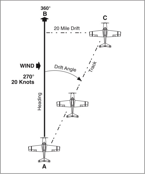
For example, Figure 9-3 shows an aircraft which departs point A on a heading of 360° and flies for 1 hour in a wind of 270° at 20 knots. Under a no-wind condition the aircraft would arrive at point B at the end of 1 hour. However, this example has a wind of 20 knots, and the aircraft moves with the wind; so at the end of 1 hour, the aircraft is at point C, 20 nautical miles downwind from B. From A to B is the intended path of the aircraft, from B to C is the motion of the body of air, and from A to C is the actual path of the aircraft over the earth (the track).
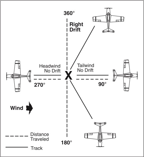
A given wind will cause a different drift on each aircraft heading and it will also affect the distance traveled over the ground in a given time. With a given wind, the ground speed varies with each different aircraft heading. Figure 9-4 illustrates how a wind of 270° at 20 knots would affect the ground speed and track of an aircraft on various headings. In this particular illustration, on a heading of 360°, drift would be to the right; on a heading of 180°, drift would be to the left. With a 90° crosswind and no heading correction applied, there would be little effect on ground speed. On a heading of 090°, no left or right drift would be experienced; instead, the ground speed would be increased by the tailwind. On a 270° heading, the ground speed would be reduced by the headwind.
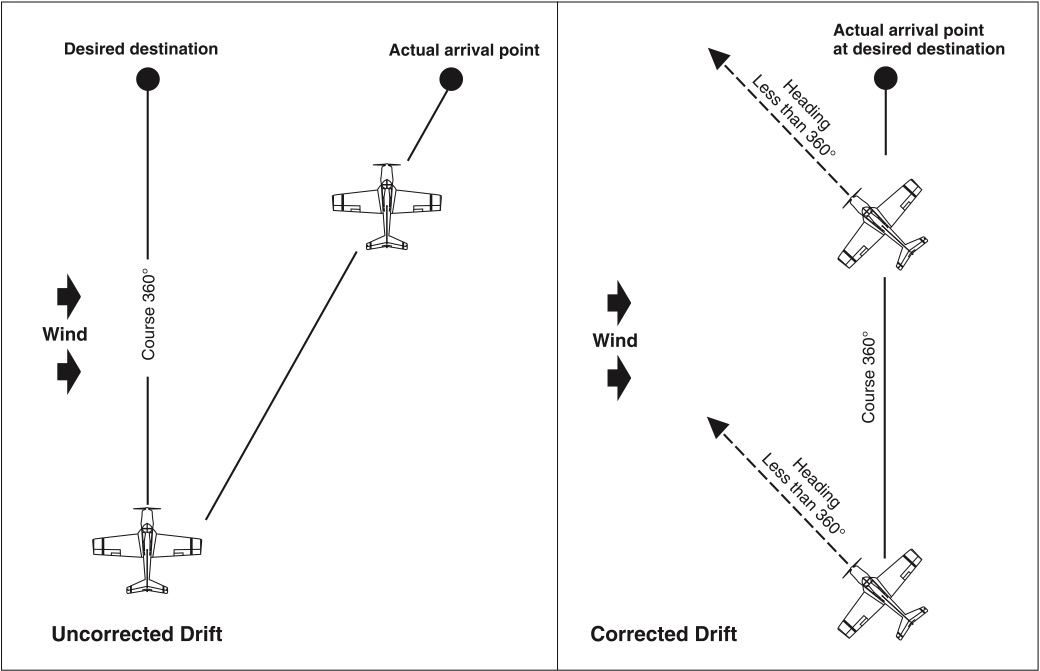
By determining the amount of drift, a pilot can counteract the effect of wind and make the track of the aircraft coincide with the desired course. For example, if the wind is from the left, the correction would be made by pointing the aircraft to the left a certain number of degrees, thereby compensating for wind drift. This is the wind correction angle (WCA), and it is expressed as degrees left or right of the course. See Figure 9-5.
Any course, true, magnetic, or compass, becomes a heading when it is corrected for wind. See Figure 9-6.

The Wind Triangle
True course is determined by measuring the course on an aeronautical chart. True airspeed is known by applying the appropriate correction to the indication of the airspeed indicator. The wind direction and velocity are known from reports or forecasts from Flight Service Stations.
The true heading and the ground speed can be found by drawing a wind triangle of vectors. One side of the triangle is the wind direction and velocity, one side is the true heading and true airspeed, the final side is the track, or true course, and the ground speed. Each side of a wind triangle is the vector sum of the other two sides.
The Flight Computer (E6-B)
Note: ASA’s CX-3 is an electronic flight computer and can be used in place of the E6-B. This aviation computer can solve all flight planning problems, as well as perform standard mathematical calculations.
Finding Wind Correction Angle (WCA) and Ground Speed (GS)
The WCA required to change a course to a heading can be found by using the wind face of the E6-B. Ground speed can also be determined as a part of this procedure.
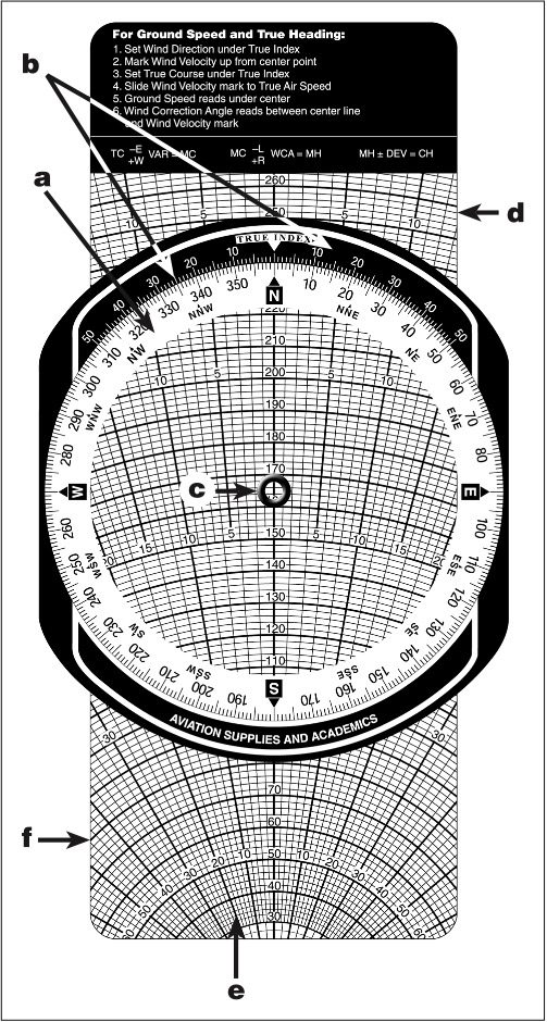
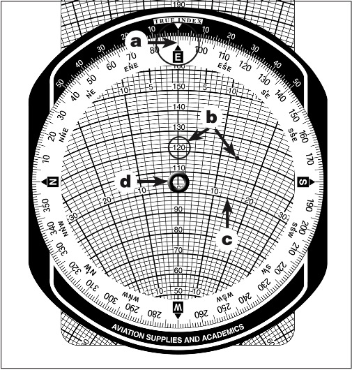
The wind face of the E6-B consists of a transparent, rotatable plotting disk mounted in a frame as shown in Figure 9-7. A compass rose is located around the plotting disk (Figure 9-7a). A correction scale on the top of the frame is graduated in degrees left and right of the true index (Figure 9-7b), and it is used for calculating drift correction. A small reference circle, called a grommet, is located at the center of the plotting disk (Figure 9-7c).
A sliding grid (Figure 9-7d) inserted behind the plotting disk is used for wind computations. The slide has converging lines (track or drift lines) which indicate degrees left or right of center (Figure 9-7e). Concentric arcs (speed circles) on the slide are used for calculations of speed (Figure 9-7f). The wind correction angle and ground speed may be found when true course, true airspeed, wind speed and wind direction (relative to true north) are known.
Problem: Using a flight computer and the following conditions, find the WCA, the true heading (TH), and the ground speed (GS).
Conditions:
Solution:
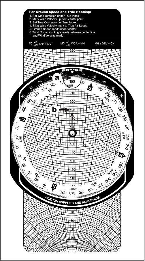
1. Using the wind face side of the E6-B, set the true wind direction (160°) under the true index (Figure 9-8a).
2. Plot the wind speed above the grommet 30 units (wind speed). Note: The sliding grid can be at any value for this step. Place a wind dot within a circle at this point (Figure 9-8b).
3. Rotate the plotting disk and set the true course (090°) under the true index (Figure 9-9a).
4. Adjust the sliding grid so that the TAS arc (120 knots) is at the wind dot (Figure 9-9b). Note the wind dot is 14° right of centerline (Figure 9-9c), so the WCA = 14°R.
5. Under the grommet, read the GS of 106 knots (Figure 9-9d).
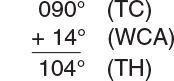
6. Determine the TH by applying the formula:
TC + WCA = TH
In this case the wind correction is to the right, so it will be added to the true course:
Flight Computer Calculator Face
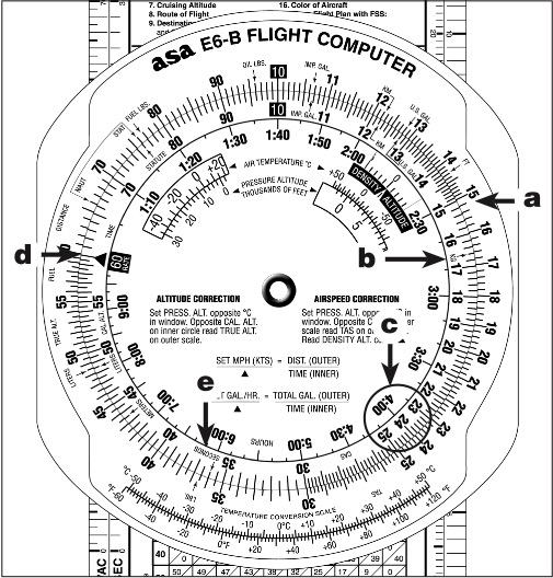
Opposite the windface of the flight computer is a circular slide rule or calculator face. The outer scale, called the miles scale, is stationary (Figure 9-10a). The inner circle rotates and is called the minutes scale (Figure 9-10b).
The numbers on the computer scale represent multiples of 10, of the values shown. For example, the number 24 on either scale may be 0.24, 2.4, 24, 240, etc. On the inner scale, minutes may be converted to hours by reference to the adjacent hours scale. In Figure 9-10c, for example, 4 hours is found adjacent to 24, meaning 240 minutes.
Relative values must be kept in mind. For example, the numbers 21 and 22 are separated by divisions, each space representing 2 units. Thus, the second division past 21 will be read as 21.4, 214, or 2,140. Between 80 and 90 are 10 divisions, each space representing 1 unit. Thus, the second division past 80 will be read as 8.2, 82 or 820.
There are three index marks on the miles (outer) scale which are used for converting statute miles (SM), nautical miles (NM) and kilometers (KM). The E6-B computer has a scale for converting statute miles, nautical miles, and kilometers. Place the known figure on the inner scale under “naut,” “stat,” or “KM,” as appropriate, and read the equivalent value under the other indexes. For example, to convert 85 statute miles to kilometers and nautical miles, place 85 on the inner scale under the “stat” index. Under the “KM” index, read 137; under the “naut” index read 74.
Each scale has a 10-index used as a reference mark for multiplication and division. The 10-index on the inner scale can also be used as a rate index representing 1 hour. Also on the inner scale is a 60-index, representing 60 minutes and usually used for computation instead of the 10 or 1 hour index (Figure 9-10d) and a 36 or “seconds” index (3,600 seconds = 1 hour) (Figure 9-10e).
Finding Time, Rate, and Distance
The flight computer will commonly be used to solve problems of time, rate, and distance. When two factors are known, the third can be found using the proportion:

Problem: How far does an aircraft travel in 2 hours and 15 minutes at a ground speed of 138 knots?
Solution: Use the formula:
Distance = Ground Speed × Time, or use the flight computer in the following manner:
1. Place the 60 (speed) index (inner scale) under 138 (outer scale).
2. Over the time of 135 minutes or 2 hours +15 minutes (inner scale), read 310 NM (on the outer scale). See Figure 9-11.
Problem: How much time is required to fly 320 NM at a ground speed of 174 knots?
Solution: Use the formula:
Time = Distance ÷ Ground Speed, or use the flight computer in the following manner:
1. Set the 60 (speed) index under 174 (outer scale).
2. Under 320 (outer scale), read 110 minutes or 1 hour 50 minutes (inner scale). See Figure 9-12.
Problem: What is the ground speed if it takes 40 minutes to fly 96 NM?
Solution: Use the formula: Ground Speed = Distance ÷ Time, or use the flight computer in the following manner:
1. Place 40 minutes (inner scale) under 96 (outer scale).
2. Over the 60 (speed) index, read 144 knots (outer scale). See Figure 9-13.
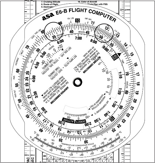
Problem: If 50 minutes are required to fly 120 NM, how many minutes are required to fly 86 NM at the same rate?
Solution:
1. Set 50 (inner scale) under 120 (outer scale).
2. Under 86 (outer scale), read 36 minutes required (inner scale). See Figure 9-14.
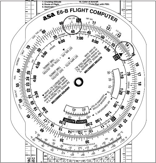
Calculating Fuel Consumption
Fuel consumption problems are solved in the same manner as time-rate-distance problems.
Problem: If 18 gallons of fuel are consumed in 1 hour, how much fuel will be used in 2 hours 20 minutes?
Solution:
1. Set the 60-index (inner scale) under 18 (outer scale).
2. Over 2 hour 20 minute (inner scale), read 42 gallons (outer scale). See Figure 9-15.
Problem: What is the rate of fuel consumption if 30 gallons of fuel are consumed in 111 minutes?
Solution:
1. Set 111 (inner scale) under 30 (outer scale).
2. Over the 60-index (inner scale), read 16.2 gallons per hour (outer scale). See Figure 9-16.
Problem: Forty gallons of fuel have been consumed in 135 minutes (2 hours and 15 minutes) flying time. How much longer can the aircraft continue to fly if 25 gallons of available fuel remain and the rate of consumption remains the same?
Solution:
1. Set 135 (inner scale) under 40 (outer scale).
2. Under 25 (outer scale), read 84.5 minutes of fuel remaining. See Figure 9-17.
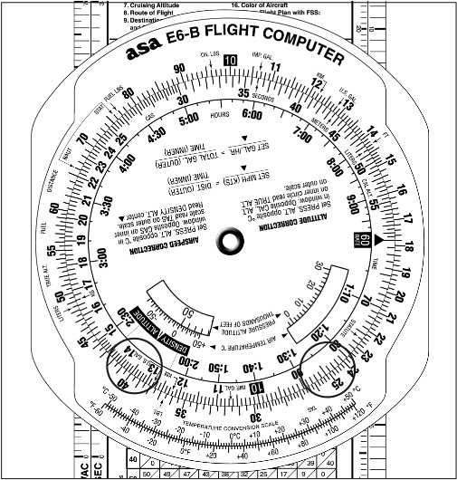
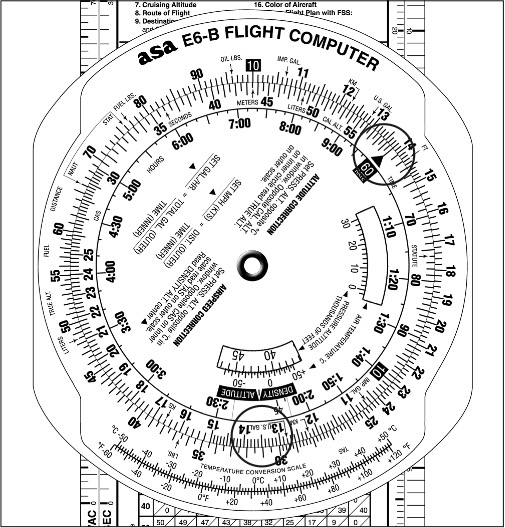
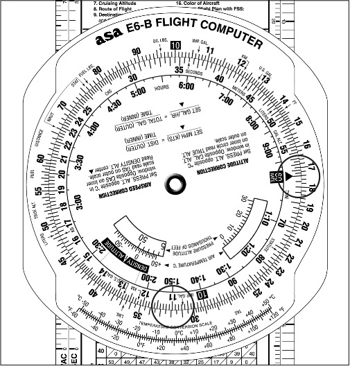
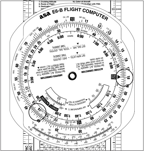
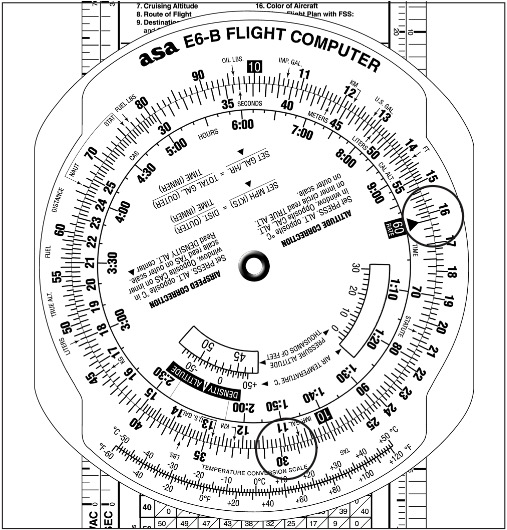
Finding True Airspeed and Density Altitude
The calculator (slide rule) side of the computer may also be used to determine true airspeed by correcting calibrated airspeed for temperature and pressure altitude. Density altitude is computed simultaneously.
Problem: Using a flight computer and the following conditions, find the TAS and the density altitude (DA).
Conditions:
Solution:
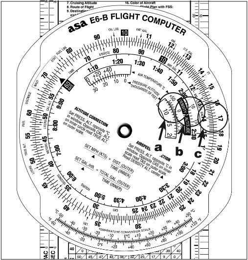
1. Using the window marked “for airspeed and density altitude computations,” place the true air temperature over the pressure altitude (Figure 9-18a).
2. In the density altitude window read the density altitude of 11,800 feet. (Figure 9-18b).
3. Over 140 knots CAS (inner scale) read the TAS of 167 knots (outer scale). See Figure 9-18c.
Airspace

Controlled airspace, that is, airspace within which some or all aircraft may be subject to air traffic control, consists of those areas designated as Class A, Class B, Class C, Class D, and Class E airspace.
Much of the controlled airspace begins at either 700 feet or 1,200 feet above the ground. The lateral limits and floors of Class E airspace of 700 feet are defined by a magenta vignette; while the lateral limits and floors of 1,200 feet are defined by a blue vignette if it abuts uncontrolled airspace. Floors other than 700 feet or 1,200 feet are indicated by a number indicating the floor.
Class A—Class A airspace extends from 18,000 feet MSL up to and including FL600 and is not depicted on VFR sectional charts. No flight under VFR, including VFR-on-top, is authorized in Class A airspace.
Class B—Class B airspace consists of controlled airspace extending upward from the surface or higher to specified altitudes. Each Class B airspace sector, outlined in blue on the sectional aeronautical chart, is labeled with its delimiting altitudes. On the Terminal Area Chart, each Class B airspace sector is, again, outlined in blue and is labeled with its delimiting arcs, radials, and altitudes. Each Class B airspace location will contain at least one primary airport. An ATC clearance is required prior to operating within Class B airspace. A pilot landing or taking off from one of a group of twelve specific, busy airports must hold at least a Private Pilot Certificate. At other airports, a student pilot may not operate an aircraft on a solo flight within Class B airspace or to, from, or at an airport located within Class B airspace unless both ground and flight instruction has been received from an authorized instructor to operate within that Class B airspace or at that airport, and the flight and ground instruction has been received within that Class B airspace or at the specific airport for which the solo flight is authorized. The student’s logbook must be endorsed within the preceding 90 days by the instructor who gave the flight training and the endorsement must specify that the student has been found competent to conduct solo flight operations in that Class B airspace or at that specific airport. Each airplane operating within Class B airspace must be equipped with a two-way radio with appropriate ATC frequencies, and a 4096 code transponder with Mode C automatic altitude-reporting capability.
Class C—All Class C airspace has the same dimensions with minor site variations. They are composed of two circles both centered on the primary airport. The inner circle (now called surface area) has a radius of 5 NM and extends from the surface up to 4,000 feet above the airport. The outer circle (now called shelf area) has a radius of 10 nautical miles and extends vertically from 1,200 feet AGL up to 4,000 feet above the primary airport. In addition to the Class C airspace proper, there is an outer area with a radius of 20 NM and vertical coverage from the lower limits of the radio/radar coverage up to the top of the approach control facility’s delegated airspace. Within the outer area, pilots are encouraged to participate but it is not a VFR requirement. Class C airspace service to aircraft proceeding to a satellite airport will be terminated at a sufficient distance to allow time to change to the appropriate tower or advisory frequency. Aircraft departing satellite airports within Class C airspace shall establish two-way communication with ATC as soon as practicable after takeoff. On aeronautical charts, Class C airspace is depicted by solid magenta lines.
Class D—Class D airspace extends upward from the surface to approximately 2,500 feet AGL (the actual height is as needed). Class D airspace may include one or more airports and is normally 4 NM in radius. The actual size and shape is depicted by a blue dashed line and numbers showing the top. When the ceiling of Class D airspace is less than 1,000 feet and/or the visibility is less than 3 SM, pilots wishing to take off or land must hold an instrument rating, must have filed an instrument flight plan, and must have received an appropriate clearance from ATC. In addition, the aircraft must be equipped for instrument flight. At some locations, a pilot who does not hold an instrument rating may be authorized to take off or land when the weather is less than that required for visual flight rules. When special VFR flight is prohibited, it will be depicted by “No SVFR” above the airport information on the chart.
Class E—Magenta shading identifies Class E airspace starting at 700 feet AGL, and no shading (or blue if next to Class G airspace) identifies Class E airspace starting at 1,200 feet AGL. It may also start at other altitudes. All airspace from 14,500 feet to 17,999 feet is Class E airspace. It also includes the surface area of some airports with an instrument approach but no control tower.
An airway is a corridor of controlled airspace extending from 1,200 feet above the surface (or as designated) up to and including 17,999 feet MSL, and 4 NM either side of the centerline. The airway is indicated by a centerline, shown in blue.
Class G—Class G airspace is airspace within which ATC has neither the authority nor responsibility to exercise any control over air traffic. Class G airspace typically extends from the surface to the base of the overlying controlled (Class E) airspace which is normally 700 or 1,200 feet AGL. In some areas of the western United States and Alaska, Class G airspace may extend from the surface to 14,500 feet MSL. An exception to this rule occurs when 14,500 feet MSL is lower than 1,500 feet AGL.
Prohibited Areas are blocks of airspace within which the flight of aircraft is prohibited.
Restricted Areas denote the presence of unusual, often invisible, hazards to aircraft such as artillery firing, aerial gunnery, or guided missiles. Penetration of Restricted Areas without authorization of the using or controlling agency may be extremely hazardous to the aircraft and its occupants.
Warning Areas contain the same hazardous activities as those found in Restricted Areas, but are located in international airspace. Prohibited, restricted, or warning areas are depicted as shown in FAA Legend 1.
Military Operations Areas (MOAs) consist of airspace established for the purpose of separating certain military training activities from IFR traffic. Pilots operating under VFR should exercise extreme caution while flying within an active MOA. Any FSS within 100 miles of the area will provide information concerning MOA hours of operation. Prior to entering an active MOA, pilots should contact the controlling agency for traffic advisories.
Alert Areas may contain a high volume of pilot training activities or an unusual type of aerial activity, neither of which is hazardous to aircraft. Pilots of participating aircraft as well as pilots transiting the area are equally responsible for collision avoidance.
Aircraft are requested to remain at least 2,000 feet above the surface of National Parks, National Monuments, Wilderness and Primitive Areas, and National Wildlife Refuges.
Military Training Routes (MTRs) have been developed for use by the military for the purpose of conducting low-altitude, high-speed training. Generally, MTRs are established below 10,000 feet MSL for operations at speeds in excess of 250 knots.
IFR Military Training Routes (IR) operations are conducted in accordance with IFR, regardless of weather conditions. VFR Military Training Routes (VR) operations are conducted in accordance with VFR. IR and VR at and below 1,500 feet AGL (with no segment above 1,500) will be identified by four digit numbers, e.g., VR1351, IR1007. IR and VR above and below 1,500 feet AGL (segments of these routes may be below 1,500) will be identified by three digit numbers, e.g., IR341, VR426.